GE HEALTHCARE
DIRECTION 2286865, REVISION 14 LOGIQ™ 7 SERVICE MANUAL
Section 5-4 - Block Diagrams and Theory 5-15
5-4-3-2 BEP4 Devices/Connectors
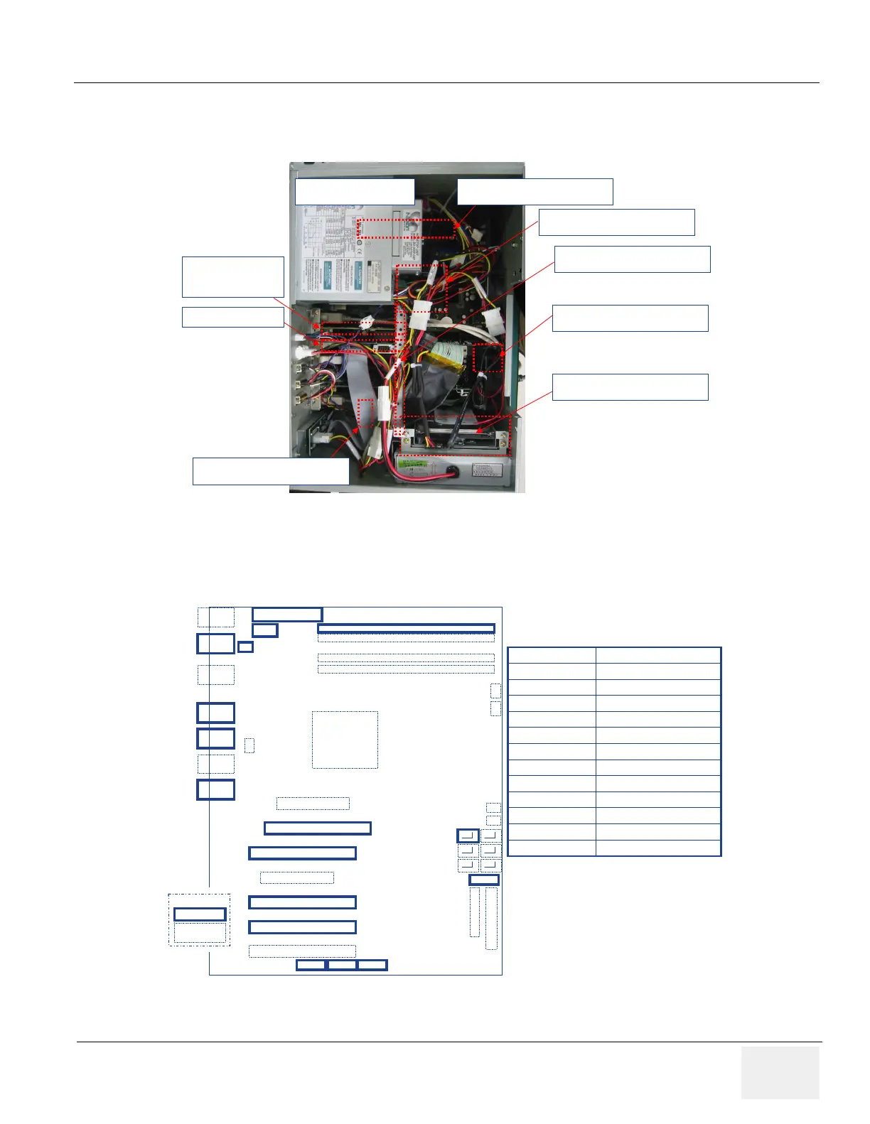
Figure 5-38 BEP4 Physical Configuration
Figure 5-39 BEP4 Components
Memory : 1GB (1/4bank)
PCI-Express
Graphics Card
PCI-DGVIC2
CPU : Core2 DUO
Mechanical “bracket” to
keep boards in place
SATA 160GB HDD
USB Header (2 ch)
USB Header (2 ch)
ATX Power Supply
CPU
PW2
Keyboard
Mouse
USB x 2
VGA
USB x 2
LAN
MIC
Line in/out
OPMA Conn
ECI-E1 - Graphics Card
PCI Slot 4 - PCIDGVIC2
PCI-E2
PCI Slot 3 - Falcon Video Capture
PCI Slot 2 - PC2IP3
PCI Slot 1
FDD / IDE
USB 5 USB 6 USB 3
CPU Fan
Fan2
Fan 5
Fan 3
Fan 6
Fan 4
SATA
LAN
Connects to CPU FanCPU Fan
PC2IP3 Comm BoardPCI-Slot 2
Falcon Video CapturePCI-Slot 3
PCI-DGVIC2PCI-Slot 4
P690 Graphics BoardPCI-E1
USB Ext. (4Ch)USB5/6
USB Ext. (2Ch, Top)USB4
USB Ext. (2Ch, Bottom)USB3
Connects to ATX PowerPW2
Connects to 160GB HDDSATA
1GB DDR2 at DIMM1 slotMemory
4 pin CPU Power ConnPW1
DescriptionDevice/Connector
PW1
BEP4 Motherboard
- Internal Connector Locations
Memory
DIMM1
DIMM2
DIMM3
DIMM4
Memory
DIMM1
DIMM2
DIMM3
DIMM4
Legend
Not Used/Not
Serviceable
Slot/Device Used
Legend
Not Used/Not
Serviceable
Not Used/Not
Serviceable
Slot/Device Used
USB 4