GE HEALTHCARE
DIRECTION 2286865, REVISION 14 LOGIQ™ 7 SERVICE MANUAL
Section 3-5 - Installation Paperwork 3-23
3-5-1-1 Rear Panel Connector (cont’d)
Pin Assignment for Camera B/W
NOTE: Output level of control signals indicated in the above tables are TTL level.
Pin Assignment of Insite
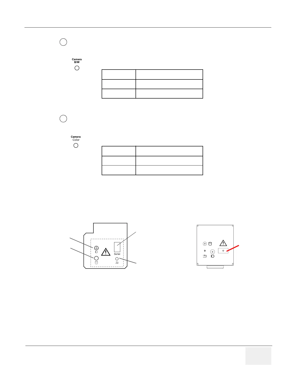
3-5-1-2 Front Connector Panel
Located on the front panel are Microphone, LED, and Reset.
Table 3-16 Pin Assignment of Mini-Jack for Controlling B/W Camera
Pin No Output Signal
1PRINT
2 Signal GND
Table 3-17 Pin Assignment of Mini-Jack for Controlling Color Camera
Pin No Output Signal
1 SHUTTER
2 Signal GND
Figure 3-9 Front Connector Panel
7
8
Reset
Microphone
LED
(HD access)
Note:USB1.1. Some
systems do NOT have this
port. If your system has
this port, do NOT use this
port! Instead, use the
USB port located at the
rear connector panel.
Serial
For BT04 or later
For BT03 or lower
You can use
the serial port.
USB2.0