GE HEALTHCARE
DIRECTION 2286865, REVISION 14 LOGIQ™ 7 SERVICE MANUAL
3-24 Section 3-5 - Installation Paperwork
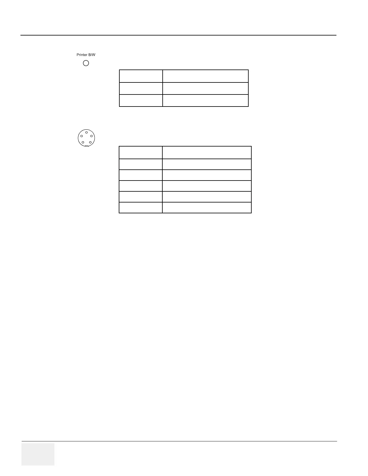
3-5-1-3 B/W Printer Connector Panel
3-5-1-4 Footswitch Connector Panel
Round 5 pin connector.
NOTE: Output level of control signals indicated in the above tables are TTL level.
Table 3-18 Pin Assignment of Mini-Jack for Controlling B/W Printer
Pin No Output Signal
1PRINT
2 Signal GND
Table 3-19 Pin Assignment of Mini-Jack for Footswitch
Pin No Output Signal
1SW1-WH
2SW2-RD
3SW3-GN
4 SW1-BK, SW2-BK, SW3-BK
5Frame GND
1
2
3
4
5