EasyManuals Logo

GE LOGIQ 7 Service Manual

GE LOGIQ 7
394 pages
To Next Page IconTo Next Page
To Previous Page IconTo Previous Page
Page #159 background imageLoading...
Page #159 background image
GE HEALTHCARE
DIRECTION 2286865, REVISION 14 LOGIQ™ 7 SERVICE MANUAL
Section 5-7 - Air Flow Control 5-43
5-7-3 Fans
The scanner contains the eight fans at the following positions for producing an air flow.
- Two fans: Inside the LV unit for air flow path A and B
- One fan: On the PC Box for air flow path A
- Four fans: At the bottom of the NEST Assy for air flow path C
- One fan: On the HV unit for air flow path D
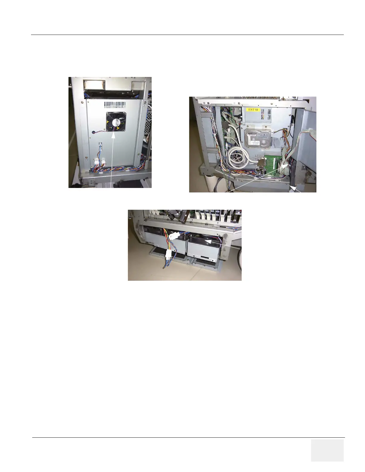
Figure 5-68 Fans
Fan for HV unit
Fan for PC Box
Fans for LV unit
Fans for NEST Assy
Example: For BT03 or lower

Table of Contents

Other manuals for GE LOGIQ 7

Questions and Answers:

Question and Answer IconNeed help?

Do you have a question about the GE LOGIQ 7 and is the answer not in the manual?

GE LOGIQ 7 Specifications

General IconGeneral
BrandGE
ModelLOGIQ 7
CategoryMedical Equipment
LanguageEnglish

Related product manuals