Disassembly
Removing the LCD
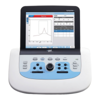
Step 5
or Softkeypad cables
Remove the nut that secures the
(continued)
grounding straps to the rear chassis.
Step 6
Place the TympStar in its normal ori-
entation and rotate the LCD forward
to expose the screw holes in the back
of the LCD enclosure.
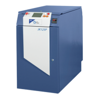
Step 7
Remove the six screws that secure the
back cover to the LCD enclosure.
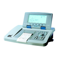
Step 8
Gently lift the LCD back cover
straight off the LCD enclosure.
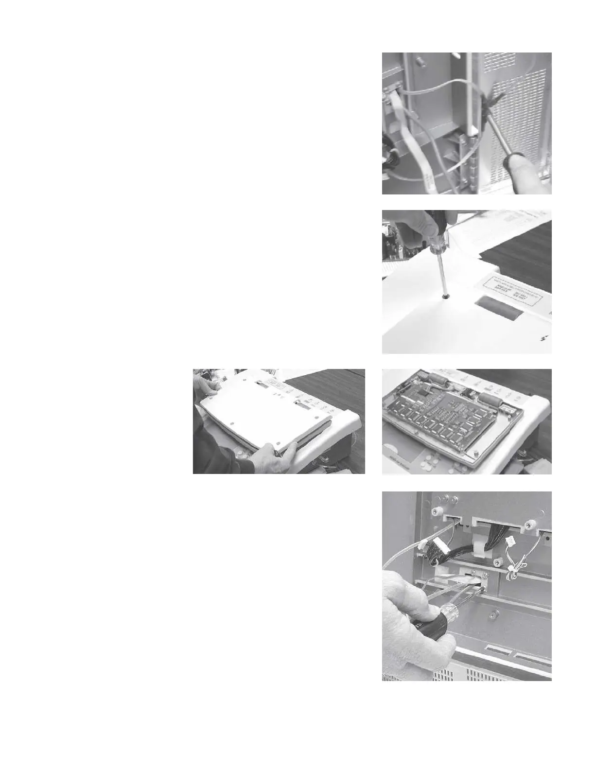
Step 9
Remove the four screws located un-
der the top panel that secure the left
LCD panel hinge.
GSI TympStar Version 1 and Version 2 Service Manual
5 - 21
 Loading...