Chapter 5
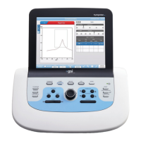
Step 10
Remove the screw located under the LCD enclosure that secures the cable
clamp to the top-left of the chassis
.
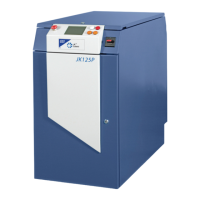
The cable clamp rests on top of a ground
cable connector and folded metal conductor.
CAUTION
The cable clamp and two conductors must be re-assembled in exactly the
same orientation.
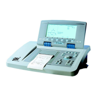
Step 11
Disconnect the inverter assembly
cable.
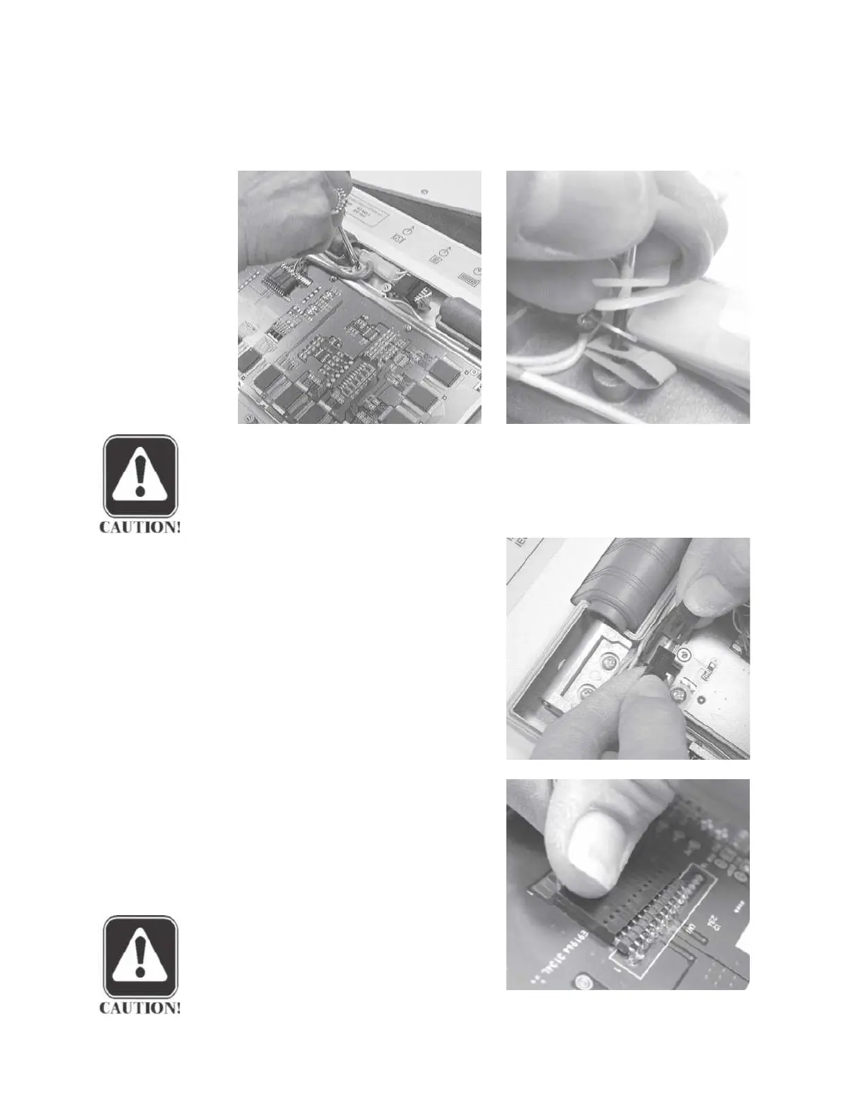
Step 12
Disconnect the 12-pin cable connec-
tor from the LCD assembly by grasp-
ing the connector firmly and gently
pulling it straight off the pins.
Gently
rock the connector back and forth as
it is pulled off the pins.
CAUTION
The brown cable wire should be
connected to pin 1 on the board
when the cable is re-installed.
Grason-Stadler
 Loading...