16-8 16. MITSUBISHI ELECTRIC PLC
FX Series (A Protocol)
*1 CN200 to CN255 equals 32CN (32-bit counter).
*2 For numerical data format where double-words can be used (Num. Data Display, Graph, Sampling), data is
processed as double-words.
For those where bits or words can be used, data is processed as words consisting of lower 16 bits.
For input Upper 16 bits are ignored.
For output “0” is written for upper 16 bits.
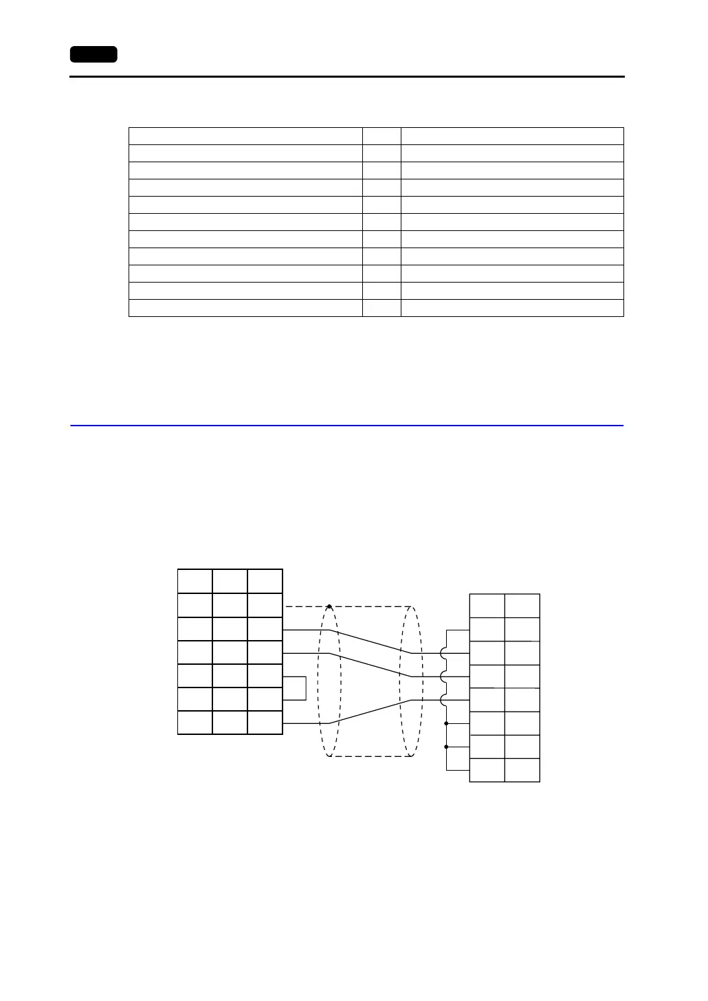
Wiring
Wiring diagrams with the PLC are shown below.
RS-232C
Wiring Diagram 1
Memory TYPE Remarks
D (data register) 0
TN (timer/current value) 1
CN (counter/current value) 2 *1
32CN (counter 32 bits) 3 *2
M (internal relay) 4
S (state) 5
X (input relay) 6 Read only
Y (output relay) 7
TS (timer/contact) 8
CS (counter/contact) 9
PLC
RD
SD
RS
CS
DR
SG
CD
1
2
3
5
6
7
8
1
2
3
4
5
7
SD
RD
RS
CS
SG
SHELL
8
7
5
*1
* Use shielded twist-pair cables.
D-sub 9-pin (male)
D-sub 25-pin (male)RJ-45 8-pin
V Series
CN1
V706
MJ2
*1 Pin No. 1 of CN1 is used
as FG.
The metal shell of the
modular jack 2 on the
V706 is used as SG.
Signal
Name
Pin No. Pin No.
Signal
Name
Pin No.