19-2 19. OMRON PLC
*1 Replace the shell on the D-sub 25-pin side before use. (Recommended part: DDK’s 17J-25)
*2 For connection to MJ2 of a V706, use an MJ2-PLC adaptor plus CQM1-CIF01.
*3 For SYSMAC CS1/CJ1 DNA, refer to page 19-8.
Communication Setting
The recommended communication parameter settings of the PLC and the V7 series are as follows:
* The maximum baud rate available with the V7 series is 115200 bps.
Select the appropriate baud rate depending on the used PLC and environment.
V-SFT Setting
Set [Trans. Mode] in the [Detail] tab window of the [Comm. Parameter] dialog of the V-SFT editor.
*1 BCD w/ signs
Data in the PLC memory can be shown as data with signs.
When higher 4 bits in the memory indicates [F] or [A], it is treated as negative.
[F]: Regards higher 4 bits as [−0].
[A]: Regards higher 4 bits as [−1].
• Displayable range 1 word: −1999 to +9999
2 words: −19999999 to +99999999
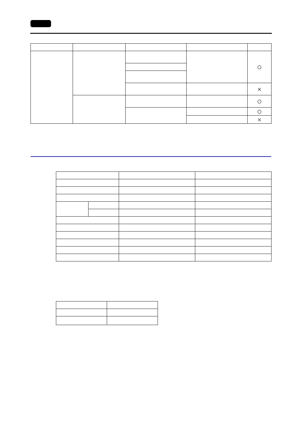
SYSMAC CS1/CJ1
SYSMAC CS1/CJ1
DNA
*3
CS1
CPU unit
(RS-232C port)
RS-232C [Wiring Diagram 2]CS1W-SCU21
Mounted on the CPU slot
(CS1W-SCB21)
Mounted on the CPU slot
(CS1W-SCB41)
RS-422 [Wiring Diagram 7]
CJ1H, CJ1M
CPU unit with built-in port
(host link port)
RS-232C [Wiring Diagram 2]
CJ1W-SCU41
RS-232C [Wiring Diagram 2]
RS-422 [Wiring Diagram 7]
Select PLC Type PLC Unit/Port Connection PLC2Way
Item Setting on PLC V7 Comm. Parameter Setting
Baud rate* 19200 bps 19200 bps
Port 0 0
Parity Even Even
Transmission
code
Data length 7 (ASCII) 7
Stop bit 2 2
Command level 3 (fixed) −
Protocol 1 : n protocol (fixed) −
Synchronizing switch Internal synchronization (fixed) −
CTS switch 0 V (always ON) (fixed) −
5 V supply switch OFF (fixed) −
Terminating resistance ON for RS-422 −
Transmission Mode Contents
Trans. Mode 1 BCD w/o sign
Trans. Mode 2
BCD w/ signs
*1