24-4 24. Siemens PLC
Available Memory
The available memory setting range varies depending on the PLC model. Be sure to set within the
range available with the PLC to be used. Use [TYPE] when assigning the indirect memory for macro
programs.
S5, S5 V4, S7
The assigned memory is indicated when editing the screen as shown below.
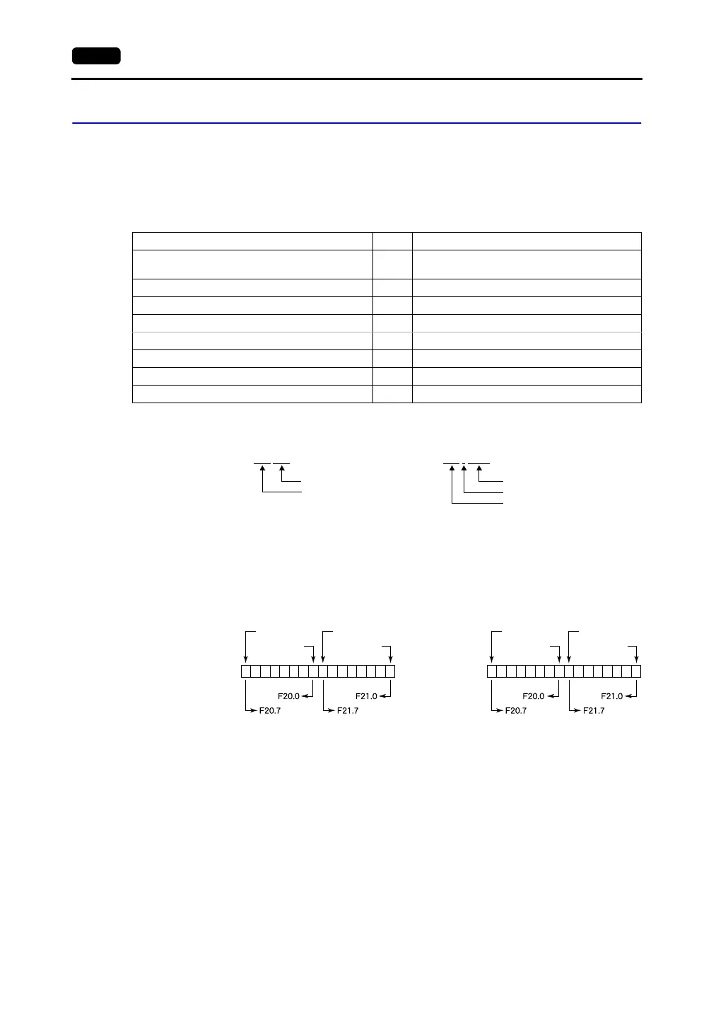
* Notes on V4 (or GD-80) data conversion
• When converting data of V4 (or GD-80) into the V7 data, [S5 V4] is automatically selected for
the PLC type.
• With V4 (or GD-80), the order of bit strings of I (input relay), Q (output relay) and F (internal
relay) is byte-reversed. Please take note of this.
Memory TYPE Remarks
DB (data register) 0
Use memory address DB1 and later for S7, or
DB3 or later for S5.
I (input relay) 1 IW as word device, read only
Q (output relay) 2 QW as word device, read only
F (flag/internal relay) 3 FW as word device, read only, only in S5 series
M (flag/internal relay) 3 MW as word device, read only, only in S7 series
T (timer/current value) 4 Read only
C (counter/current value) 5 Read only
AS (absolute address) 6 Unavailable with the S7 series
DB003 000
Address
Block number
Example: For S5, S5 V4:
DB003
: 0000
Address
Colon
Block number
For S7:
15 14 13 12 11 10
9 8 7 6 5 4 3 2 1 0
F0000210
F0000217
F0000200
F0000207
15 14 13 12 11 10
9 8 7 6 5 4 3 2 1 0
F0000200
F0000207
F0000210
F0000217
Memory setting of
V4 (or GD-80)
Memory to be
accessed to PLC
by V4 (or GD-80)
Memory setting of
V7
Memory to be
accessed to PLC
by V7
Example: For S5 V4: For S5, S7:
FW20FW20