App4-2 Appendix 4 1 : n Connection (Multi-drop)
Wiring (RS-422/485)
For connecting information, refer to the instruction manual for the PLC.
Example:
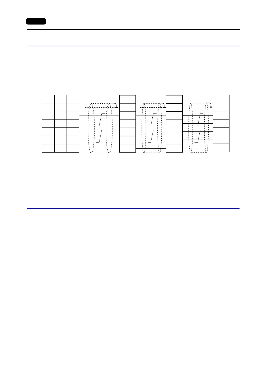
The following example shows how one V7 series is connected to three PLCs made by
MITSUBISHI.
For more information, refer to MITSUBISHI’s instruction manual for the PLC.
V-SFT Setting
The following settings must be made on the V-SFT editor.
Only the points different from those described in “V-SFT Setting (1 : 1 Connection)” (page 1-10) are
explained here.
PLC Selection
Select the PLC that is connected. Check that the PLC to be connected is ready for 1 : n connection.
Refer to the “Appendix.”
• Setting Procedure
[System Setting] → [PLC Type] → [Select PLC Type] dialog
Communication Parameter Setting
• Setting Procedure
[System Setting] → [Comm. Parameter] → [Comm. Parameter] dialog
• Setting Items
Select “1 : n” for [Connection].
PLC Port Setting
Set the port number of each PLC not in the [Comm. Parameter] dialog but in the [Memory Setting]
dialog for each part.
FG
RDA
RDB
SDA
SDB
SG
FG
RDA
RDB
SDA
SDB
SG
FG
RDA
RDB
SDA
SDB
SG
1
7
12
13
24
25
SG
+SD
-SD
+RD
-RD
5
1
2
7
8
SHELL
*1
* Use shielded twist-pair cables.
RD terminating resistance
(ON)
Link unit Link unit Link unit
Signal
Name
Signal
Name
Terminating resistance
(OFF)
Terminating resistance
(OFF)
Terminating resistance
(ON)
Signal
Name
V Series
CN1
V706
MJ2
*1 Pin No. 1 of CN1 is used as FG.
The metal shell of the modular jack
2 on the V706 is used as SG.
Signal
Name
Pin No. Pin No.