App2-2 Appendix 2 n : 1 Connection (Multi-link 2)
• This multi-link connection is available with almost all the PLC models that support 1 : 1 connection
(refer to the “Appendix”).
(The connection between the master station and the PLC is the same as the one for 1 : 1
connection.)
• Use the RS-485 2-wire connection between stations of the V7 series. Please use Hakko
Electronics’ multi-link 2 master cable (V6-MLT) for connection between the master station (local
port 1) and the slave station (local port 2).
• In the following cases, multi-link 2 connection is not available.
1. A communication interface unit (example: OPCN-1, CC-LINK, Ethernet, etc) is used.
2. The V6 series (master or slave station) is used for the temperature control network or
PLC2Way function.
• The V7 and V6 series can be used together. The V6 series can be the master station.
(However, when V606/V606i is the master station, the slave station must be V606/V606i. Also,
depending on the hardware version of the V6 series, multi-link 2 connection may not be supported.
Refer to the V6 Hardware Specifications.)
Wiring
Connection
For V7 Series:
(a) Connection between PLC ↔ V7 master station
The communication parameter setting and connecting method are the same as those for 1 : 1
connection.
(Refer to “Chapter 2” to “Chapter 33.”)
(b)(c) Connection between V7 series master station ↔ V7 slave station
The connecting port for the V7 series master station depends on the selection for [Multi-Link]
(either [Modular Jack 1] or [Modular Jack 2]) on the V-SFT editor. Selection of [Modular Jack
2] is recommended. ([Editor Port] is set as default for [Modular Jack 1].)
The connecting port of the V7 series slave station should be CN1. It is recommended that
CN1 be equipped with a terminal converter “TC485” (set to 2-wire connection).
The multi-link 2 master cable (b) (V6-MLT) is 3 m long.
If the distance (c) between the V7 series master station and the V7 series slave station is
longer than 3 m, use a terminal block and connect the cables.
(d)(e) Connection between V7 series slave station ↔ V7 slave station
Use the RS-485 2-wire connection.
It is recommended that CN1 be equipped with a terminal converter “TC485” (set to 2-wire
connection).
(b)(c)(d)(e) The maximum length between V7 series should be 500 m.
* To avoid line-noise problems, connect one terminal only so that the shielded frame ground of each
cable will not be connected between the V7 series.
The shielded frame ground of V6-MLT must be connected to the V7 series master station.
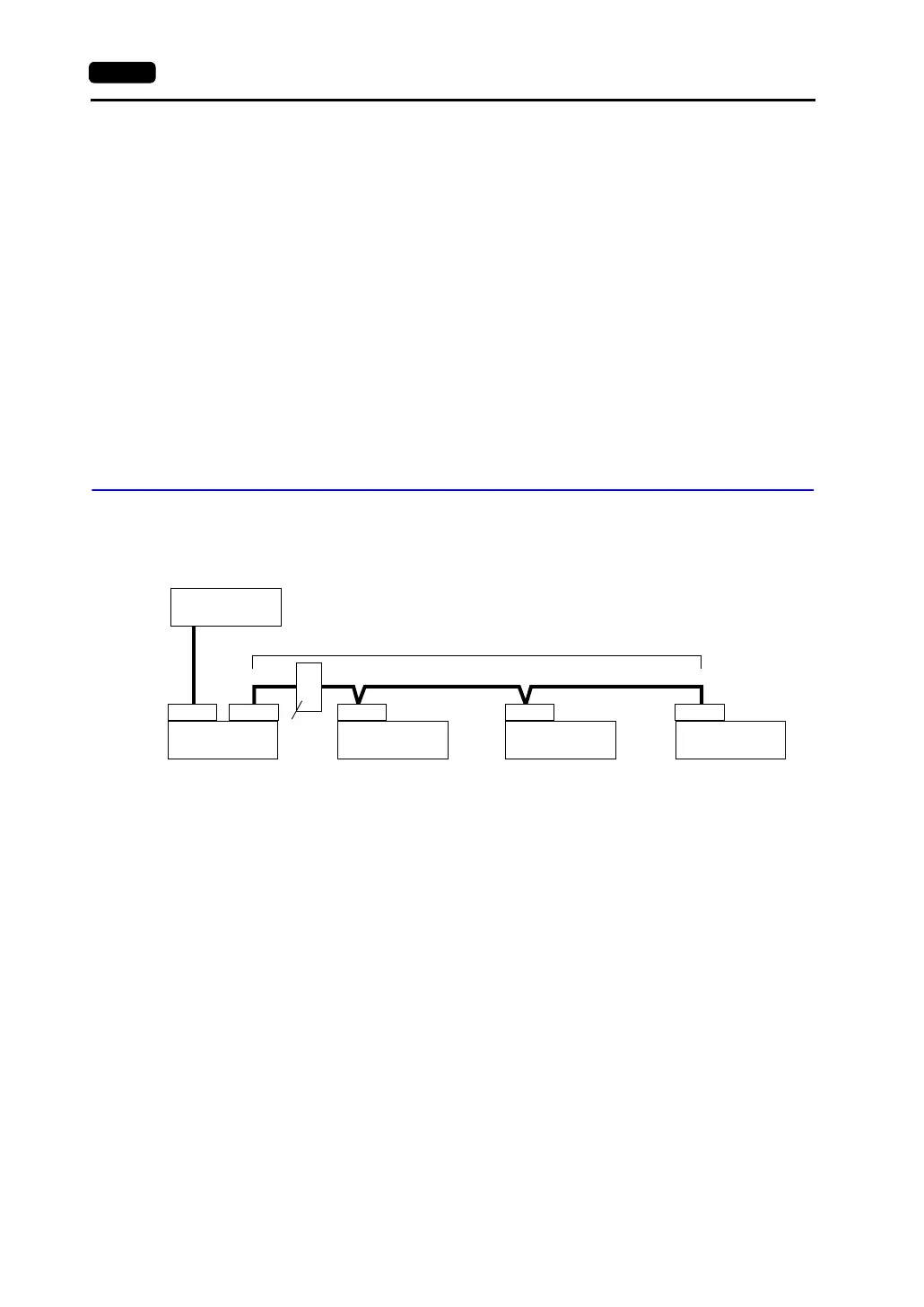
PLC
CN1CN1 MJ2
(a)
(b)
(c)
(d) (e)
CN1CN1
Communications between V7 series: RS-485 (2-wire), maximum length = 500 m
V7 master station
(= Local Port 1)
V7 slave station
(= Local Port 2)
V7 slave station
(= Local Port 3)
V7 slave station
(= Local Port 4)
Te rm i na l
block