2. Allen-Bradley PLC 2-1
2. Allen-Bradley PLC
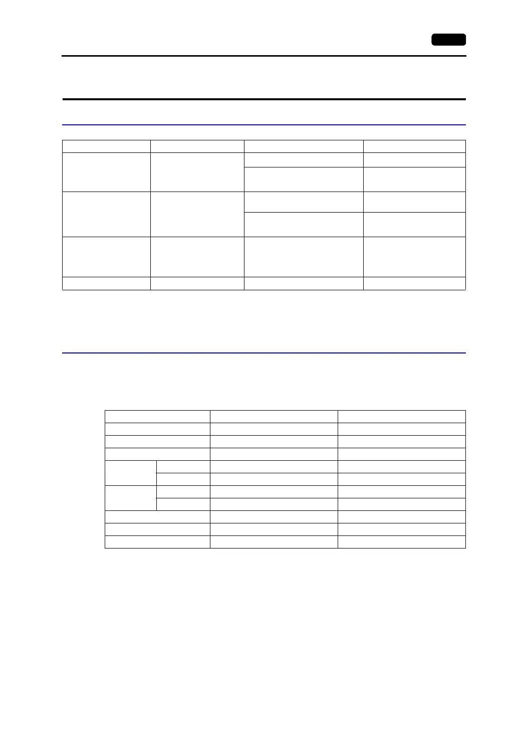
Available PLCs
*1 When using RS-232C ladder transfer cable made by Allen-Bradley, connect the cable shown in [Wiring
Diagram 3] to the D-sub 9-pin side of the ladder transfer cable for communications with the V7 series.
*2 For more information on connection to A•B Control Logix, refer to “Connection with A•B Control Logix”
separately provided.
Communication Setting
The recommended communication parameter settings of the PLC and the V7 series are as follows:
PLC-5 Series
Select PLC Type PLC Unit/Port Connection
PLC-5 PLC-5
1785-KE
RS-232C [Wiring Diagram 1]
1770-KF2
RS-232C [Wiring Diagram 2]
RS-422 [Wiring Diagram 6]
SLC500 SLC 5/03 and later
CPU (processor module)
RS-232C channel
RS-232C [Wiring Diagram 3]
1747-KE
RS-232C [Wiring Diagram 4]
RS-422 [Wiring Diagram 7]
Micro Logix 1000 Micro Logix 1000 Port on CPU
A•B’s RS-232C
Ladder transfer cable
*1
+
RS-232 [Wiring Diagram 5]
Control Logix Control Logix 1756 system Logix5550
*2
Item Setting on PLC V7 Comm. Parameter Setting
Baud rate 19200 bps 19200 bps
Port 0 0
Parity Even Even
Transmission
mode
RS-232C −−
RS-422 1785-KE not supported −
Transmission
code
Data length 8 8
Stop bit 1 1
Protocol Full duplex (fixed) −
Error check BCC (fixed) −
Reponse NO (fixed) −