App1-6 Appendix 1 PLC2Way
For V706:
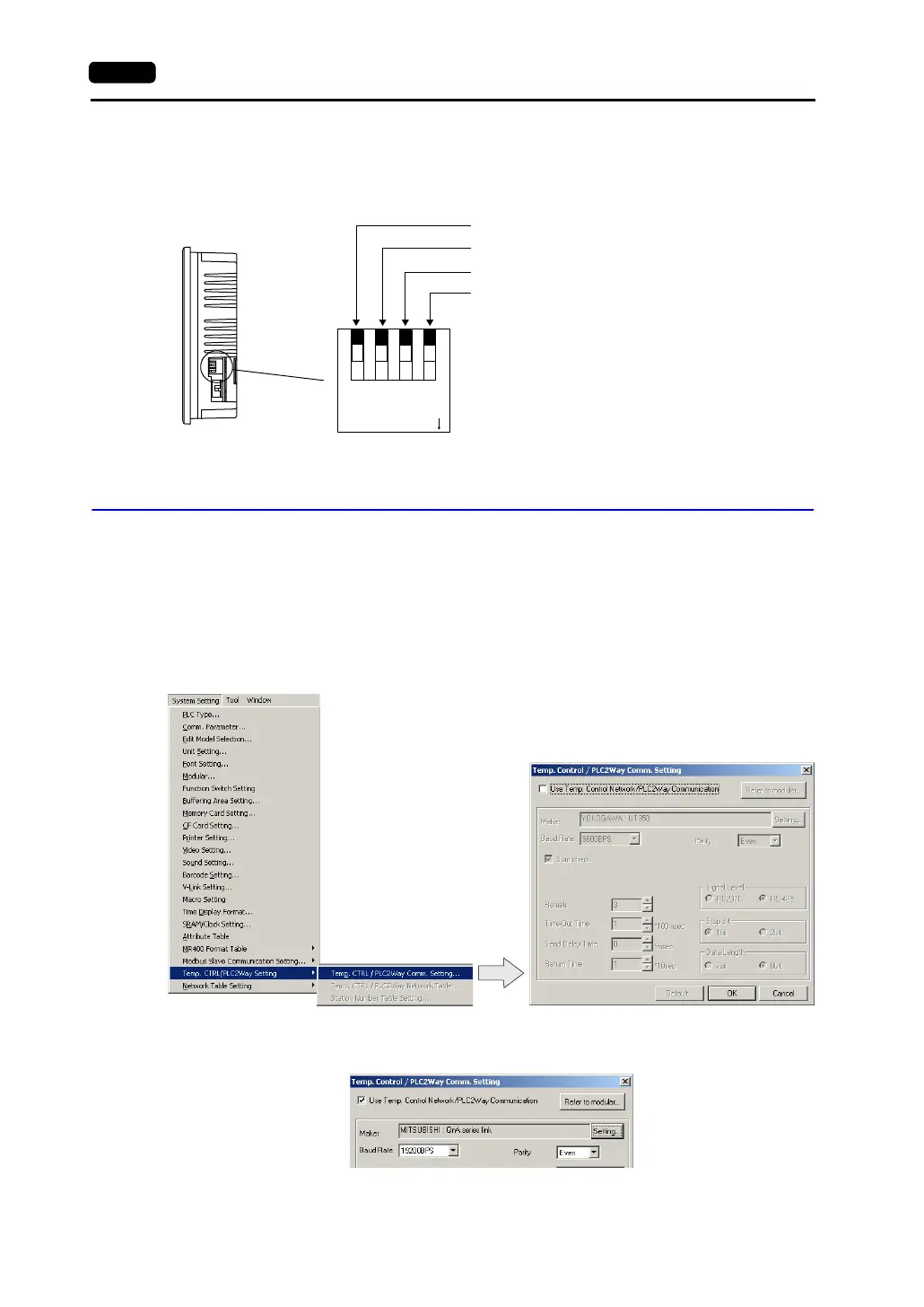
• The terminating resistance should be set on the DIP switch in the side of the unit.
• Set DIPSW1 to the ON position.
V-SFT Setting: System Setting
PLC model selection and parameter setting to be made on the V-SFT editor for the PLC2Way
connection at the MJ port are explained.
Temp. CTRL/PLC2Way Setting
Select the PLC model and make the parameter setting as described below.
1. Select [System Setting] → [Temp. CTRL/PLC2Way Setting] → [Temp. CTRL/PLC2Way Comm.
Setting]. The [Temp. Control/PLC2Way Comm. Setting] dialog is displayed.
2. Check [Use Temp. Control Network/PLC2Way Communication].
1234
ON
Side View
(Enlarged view)
CF auto load (for USB/DU-01)
MJ2 (modular jack 2) SD terminating resistance for RS-422
MJ1 (modular jack 1) terminating resistance for RS-485
MJ2 (modular jack 2) RD terminating resistance for RS-422