14-4 14. LG PLC
Wiring
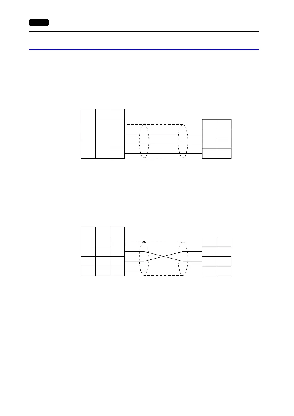
Wiring diagrams with the PLC are shown below.
RS-232C
Wiring Diagram 1
Wiring Diagram 2
PLC
RXD
TXD
GND
2
3
5
1
2
3
SD
RD
SHELL
8
7
*1
7SG 5
* Use shielded twist-pair cables.
D-sub 9-pin (male)
D-sub 25-pin (male)RJ-45 8-pin
V Series
CN1
V706
MJ2
*1 Pin No. 1 of CN1 is used
as FG.
The metal shell of the
modular jack 2 on the
V706 is used as SG.
Signal
Name
Pin No. Pin No.
Signal
Name
Pin No.
PLC
TXD
RXD
GND
2
3
7
1
2
3
SD
RD
SHELL
8
7
*1
7SG 5
* Use shielded twist-pair cables.
D-sub 25-pin (male)
D-sub 25-pin (male)RJ-45 8-pin
V Series
CN1
V706
MJ2
*1 Pin No. 1 of CN1 is used
as FG.
The metal shell of the
modular jack 2 on the
V706 is used as SG.
Signal
Name
Pin No. Pin No.
Signal
Name
Pin No.