8. Fuji Electric PLC 8-3
Available Memory
The available memory setting range varies depending on the PLC model. Be sure to set within the
range available with the PLC to be used. Use [TYPE] when assigning the indirect memory for macro
programs.
MICREX-F Series
*1 For numerical data format where double-words can be used (Num. Data Display, Graph, Sampling), data is
processed as double-words.
For those where bits or words can be used, data is processed as words consisting of lower 16 bits.
For input: Upper 16 bits are ignored.
For output: “0” is written for upper 16 bits.
*2 Byte device such as step relay is processed as described below.
For input: Upper 8 bits are “0.”
For output: Lower 8 bits are written.
*3 To set up the file memory on the V-SFT editor, enter “file number” +
“: (colon)” + “address” in order.
* Notes on V4 (or GD-80) data conversion
When converting data of V4 (or GD-80) into the V7 data, [MICREX-F series V4] is automatically
selected for the PLC type.
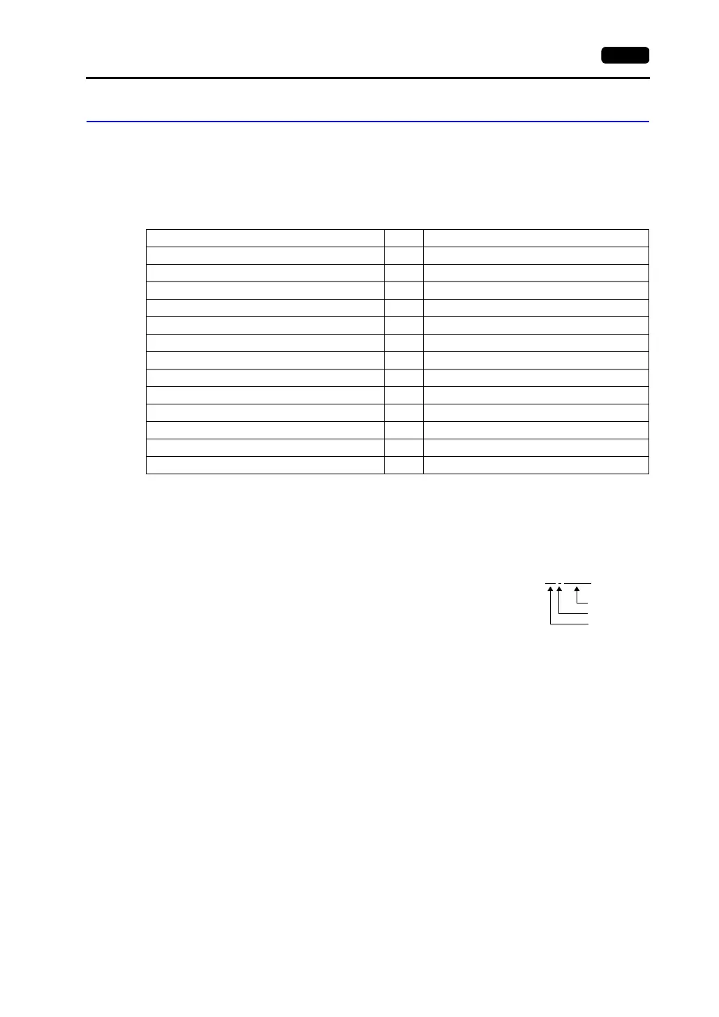
Memory TYPE Remarks
M (auxiliary relay) 0 WM as word device
K (keep relay) 1 WK as word device
B (input/output relay) 2 WB as word device
L (link relay) 9 WL as word device
F (special relay) 10 WF as word device
TS (timer/set value) 11 *1
TR (timer/current value) 12 *1
W9 (timer/current value 0.1) 13 *1
CS (counter/set value) 14 *1
CR (counter/current value) 15 *1
BD (data memory) 16 *1
WS (step control relay) 17 *2
Wn (file memory) 18 *3
Example: W30 : 00002
Address
Colon
File number