19-4 19. OMRON PLC
SYSMAC CS1/CJ1, SYSMAC CS1/CJ1 DNA
*1 When using EMn (extended data memory), specify the bank
number (CS1: 0 to C).
The assigned memory is indicated when editing the screen as
shown on the right.
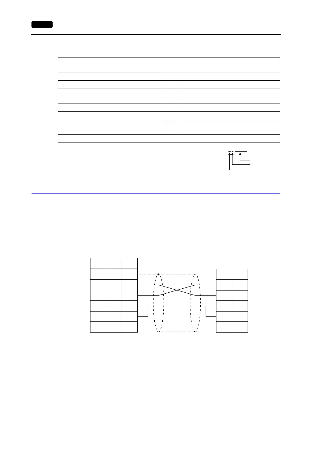
Wiring
Wiring diagrams with the PLC are shown below.
RS-232C
Wiring Diagram 1
Memory TYPE Remarks
DM (data memory) 0
CH (input/output relay) 1
H (holding relay) 2
A (alarm relay) 4
T (timer/current value) 5
C (counter/current value) 6
EMn (extended data memory) 7 *1
W (internal relay) 8
TU (timer/contact) 9 Read only
CU (counter/contact) 10 Read only
Example: EM0 : 30000
Address
Colon
Bank number
RS
SD
CS
SG
2
4
5
7
RD 3
PLC
1
2
3
4
5
7
SD
RD
RS
CS
SG
SHELL
8
7
5
*1
* Use shielded twist-pair cables.
D-sub 9-pin (male)
D-sub 25-pin (male)RJ-45 8-pin
V Series
CN1
V706
MJ2
*1 Pin No. 1 of CN1 is used
as FG.
The metal shell of the
modular jack 2 on the
V706 is used as SG.
Signal
Name
Pin No. Pin No.
Signal
Name
Pin No.