App1-4 Appendix 1 PLC2Way
Wiring
Two kinds of cables are available for PLC2Way connection at the MJ port. Cable connections are
explained.
Connecting Method 1 (Using MJ-D25)
• To connect the PLC and the V7 series at the MJ port, use Hakko Electronics’ MJ to D-sub
conversion cable “MJ-D25” (0.3 m, metric thread) and the cable for 1 : 1 connection at CN1.
For more information on the cable for 1 : 1 connection at CN1, refer to “Wiring” in “Chapter 2” to
“Chapter 33.”
• This combination of cables (MJ-D25 + 1 : 1 connection cable) can be used either for RS-232C or
RS-485 (RS-422) 2-wire connection.
• With RS-485 (2-wire connection), a maximum of 31 PLCs can be connected.
For information on connection between PLCs, refer to the instruction manual for the PLC.
Connecting Method 2 (Using V6-TMP)
• Use Hakko Electronics’ cable “V6-TMP” (3 m) when connecting the V7 series to a PLC at the MJ
port.
The shielded cable of V6-TMP is connected to FG (frame ground) when the V7 series is used and
to SG (signal ground) when the V706 is used.
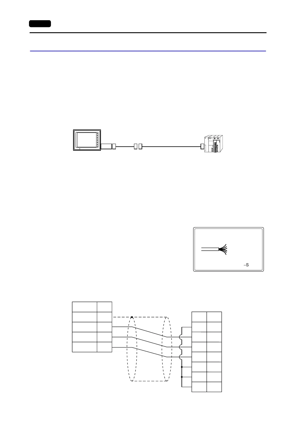
* Notes on Use of V6-TMP
There are six wires in the V6-TMP cable as shown
on the right.
The wires to be used are determined depending on
the connecting method.
For the wires not used, be sure to properly insulate
with tape, etc.
<RS-232C Connection>
• Connection example with MITSUBISHI A1SJ71UC24-R2
(RS-232C, RS-485/RS-422)
MJ2/1
F1
F2
F3
F4
F5
F6
F7
SYSTEM
POWER
MJ-D25
1 : 1 connection cable
V7 series
: 0V SG
: RD
: SD
: +5V
: +SD/RD
:
-
SD/RD
V6-TMP
Brown
Red
Orange
Yellow
Black
Green
PLC
*1
SD
RD
SG
8
7
5
RD
SD
RS
CS
DR
SG
CD
1
2
3
5
6
7
8
* Use shielded cables.
Modular jack, 8-pin
(Yellow)
(Orange)
(Red)
*1 V6-TMP is connected to FG
when the V7 series is used and
to SG when the V706 is used.
Signal Name Pin No.
Signal
Name
Pin No.