27. TOSHIBA PLC 27-3
Wiring
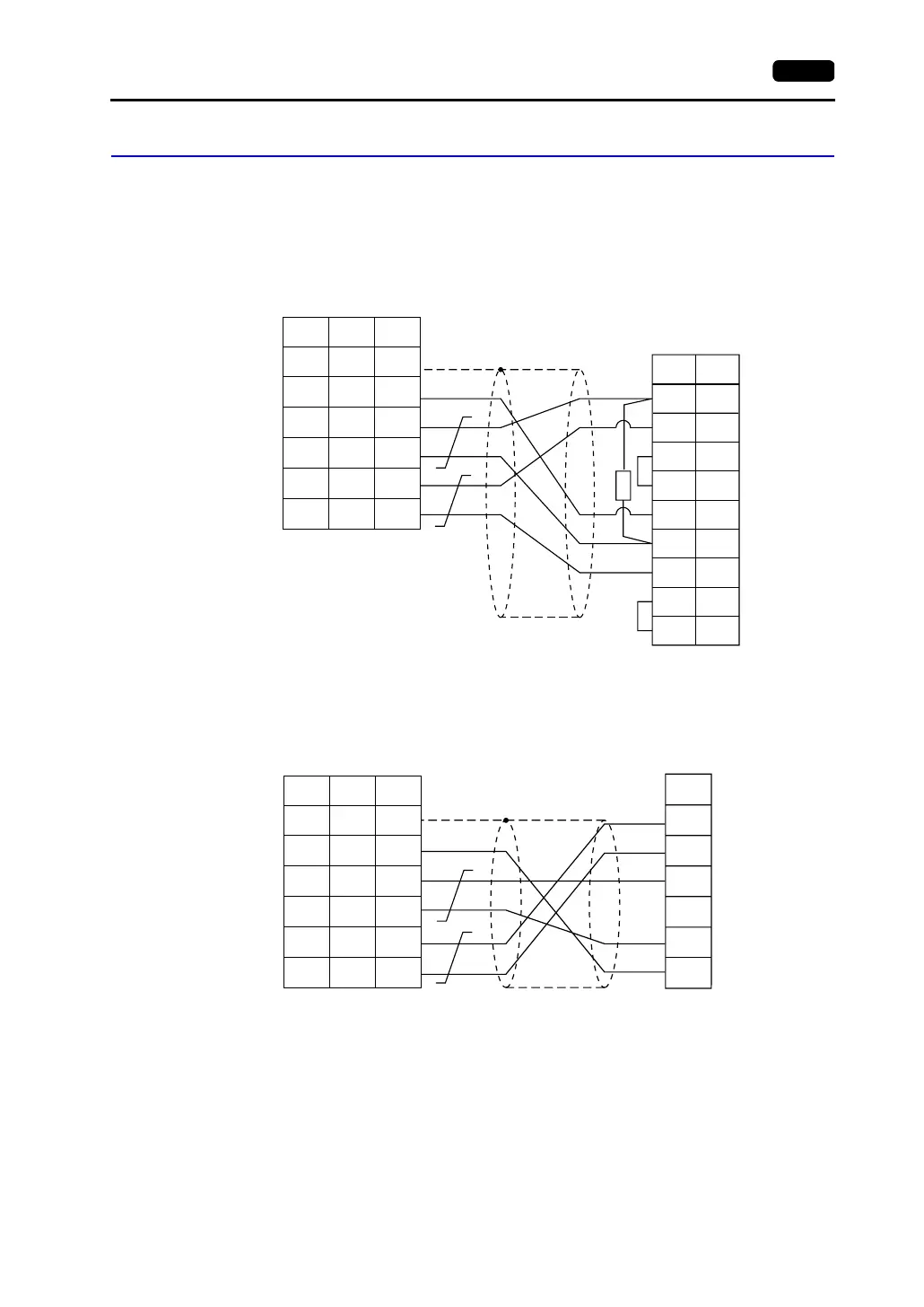
Wiring diagrams with the PLC are shown below.
RS-422
Wiring Diagram 1
Wiring Diagram 2
2
PLC
3
4
RXA
TXA
CTSA
RTSA
5
SG7
10
11
12
13
RXB
TXB
CTSB
RTSB
*
R
* R: 120 Ω 1/2W
1
7
12
13
24
25
SG
+SD
-SD
+RD
-RD
5
1
2
7
8
SHELL
*1
* Use shielded twist-pair cables.
D-sub 15-pin (male)
D-sub 25-pin (male)RJ-45 8-pin
V Series
CN1
V706
MJ2
*1 Pin No. 1 of CN1 is used
as FG.
The metal shell of the
modular jack 2 on the
V706 is used as SG.
Signal
Name
Pin No. Pin No.
Signal
Name
Pin No.
PLC
TXA
TXB
RXA
TERM
RXB
SG
1
7
12
13
24
25
SG
+SD
-SD
+RD
-RD
5
1
2
7
8
SHELL
*1
* Use shielded twist-pair cables.
D-sub 25-pin (male)RJ-45 8-pin
V Series
CN1
V706
MJ2
*1 Pin No. 1 of CN1 is used
as FG.
The metal shell of the
modular jack 2 on the
V706 is used as SG.
Signal
Name
Pin No. Pin No.
Signal
Name