10. Hitachi PLC 10-1
10. Hitachi PLC
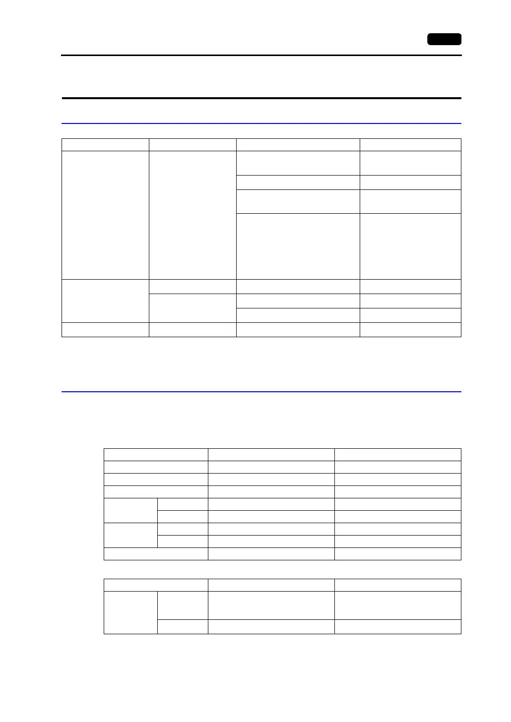
Available PLCs
*1 When using the HITACHI’s EH-RS05 or CNCOM-05 cable, connect the cable shown in [Wiring Diagram 1] to
the D-sub 15-pin side for communications with the V7 series.
*2 Specify the absolute memory address. For more information, refer to the instruction manual for the PLC.
Communication Setting
The recommended communication parameter settings of the PLC and the V7 series are as follows:
COMM-2H
If the transmission mode is any type other than listed the above, set the mode as shown below.
*1 Multi-link connection is not available.
Select PLC Type PLC Unit/Port Connection
HIDIC-H HIDIC H series
COMM-2H
RS-232C [Wiring Diagram 1]
RS-422 [Wiring Diagram 4]
Peripheral port 1 on the CPU module
RS-232C [Wiring Diagram 1]
EH150
HITACHI’s EH-RS05 cable
*1
+
RS-232C [Wiring Diagram 1]
On H-252C CPU module
PERIPHERAL 1
RS-232C
[Wiring Diagram 1]
PERIPHERAL 2
HITACHI’s CNCOM-05
cable
*1
+ RS-232C
[Wiring Diagram 1]
HIDIC-S10/2α
S10 2α Interface on the CPU unit
RS-422 [Wiring Diagram 5]
S10 mini
RS-232C connector on the CPU unit
RS-232C [Wiring Diagram 2]
LQE060
RS-232C [Wiring Diagram 3]
HIDIC-S10/ABS
ABS
*2
RS-422 [Wiring Diagram 5]
Item Setting on PLC V7 Comm. Parameter Setting
Baud rate 19200 bps 19200 bps
Port 0 for both ST No ×10, ×10
Parity Even Even
Transmission
mode
RS-232C MODE7 Protocol 2 with port
RS-422 MODE9 Protocol 2 with port
Transmission
code
Data length 7 (ASCII) 7
Stop bit 1 1
Sumcheck Provided (fixed) −
Item Setting on PLC V7 Comm. Parameter Setting
Transmission
mode
RS-232C
MODE1
MODE2
MODE9
Protocol 1 without port
Protocol 1 with port
Protocol 2 without port
RS-422 MODE2
Protocol 1 with port
*1