16-12 16. MITSUBISHI ELECTRIC PLC
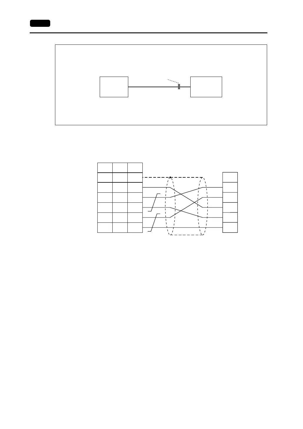
Wiring Diagram 8
According to our noise tests, the attachment of a ferrite core improves noise voltage by 650 to 900 V and aids in
preventing communication errors.
• When connecting to the A/QnA series CPU directly, attach a ferrite core to the communication cable between
the V7 series and A/QnA series CPU to avoid noise problems.
• Ferrite cores are optionally available.
When ordering the ferrite core, state “GD-FC (ID: 8 mm, OD: 20 mm).”
• In consideration of such noise problems, it is recommended that the standard type link unit be used when the
cable length of 15 m or longer is required.
V7 series
Ferrite core
A/QnA series
CPU
PLC
RDA
SG
RDB
SDB
SDA
1
7
12
13
24
25
SG
+SD
-SD
+RD
-RD
5
1
2
7
8
SHELL
*1
* Use shielded twist-pair cables.
D-sub 25-pin (male)RJ-45 8-pin
V Series
CN1
V706
MJ2
*1 Pin No. 1 of CN1 is used
as FG.
The metal shell of the
modular jack 2 on the
V706 is used as SG.
Signal
Name
Pin No. Pin No.
Signal
Name