16-14 16. MITSUBISHI ELECTRIC PLC
• Network specifying macro............... [OUT_ENQ] of system call [SYS]
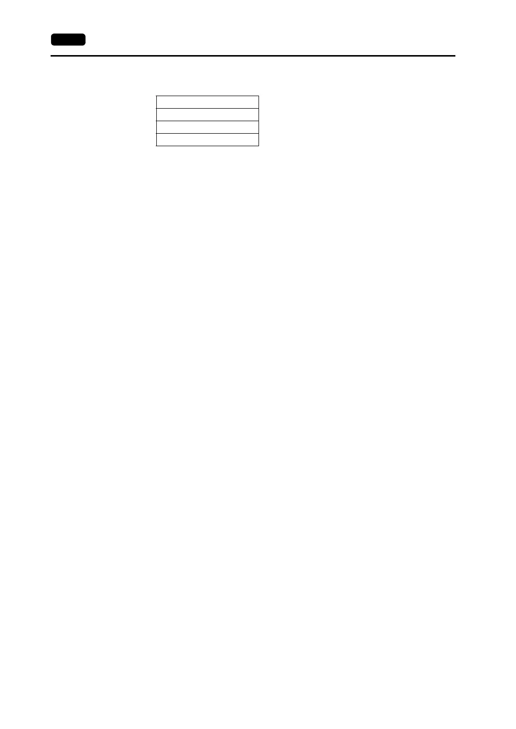
F1 memory
“n + 0” and “n + 1” are fixed to “0” and “2”, respectively.
“n + 2” (system code) should be: 1: NET/10 2: NET II (/B)
For “n + 3” (network number), set “0” when NET II (/B) is selected for “n + 2” (system code) or
the network number to be accessed when NET/10 is selected.
Do not use this macro for any purpose other than OPEN macro for a screen. Doing so triggers
network switching at the time of macro execution, resulting in a communication error.
For more information on the macro function, refer to the Reference Manual (Function).
Also refer to the explanation on network registration contained in the operation manual for
MITSUBISHI’s Standard Link/Multi-drop Link Unit.
• For the NET II (/B) data link system and NET/10 network system, refer to MITSUBISHI’s manual.
Available Memory
For the available memory of the PLC to be accessed, refer to “Available Memory” (page 16-6).
Note that the CPU number must be set on the V-SFT editor.
Wiring
Refer to the wiring diagram with the standard type link unit.
n + 0 Always 0
n + 1 Network selection: 2
n + 2 System code
n + 3 Network number