24-10 24. Siemens PLC
Wiring Diagram 7
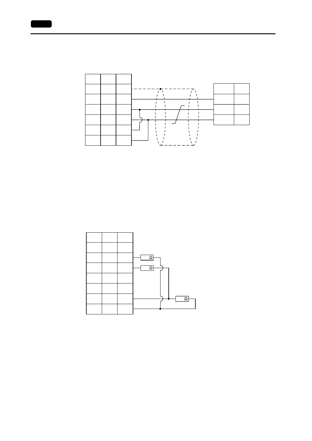
• Terminating Resistance Setting
Set the DIP switch 7 of the V series (for V706: No. 3) to the OFF position.
Connect terminating resistance to the serial connector of the V series as shown below.
If the terminating resistance is not connected, a communication error may occur.
SG
PLC
+TxD/RxD
−TxD/RxD
5
3
8
1
7
12
13
24
25
SG
+SD
-SD
+RD
-RD
5
1
2
7
8
SHELL
*1
* Use shielded twist-pair cables.
D-sub 9-pin (male)
D-sub 25-pin (male)RJ-45 8-pin
V Series
CN1
V706
MJ2
*1 Pin No. 1 of CN1 is used
as FG.
The metal shell of the
modular jack 2 on the
V706 is used as SG.
Signal
Name
Pin No. Pin No.
Signal
Name
Pin No.
390
390
220
*1
SG
5V
−SD
+RD
+SD
−RD
3
5
1
2
7
8
SHELL
9
7
12
13
24
25
1
D-sub 25-pin (male)RJ-45 8-pin
V Series
CN1
V706
MJ2
Signal
Name
Pin No.Pin No.
*1 Pin No. 1 of CN1 is used
as FG.
The metal shell of the
modular jack 2 on the
V706 is used as SG.