Appendix 1 PLC2Way App1-21
Details
• $s729
An execution result of macro command TEMP_READ, TEMP_WRITE, or TEMP_CTL is stored at
this address.
- [0]: A command has been executed successfully.
- [Other than “0”]: A command execution has resulted in an error.
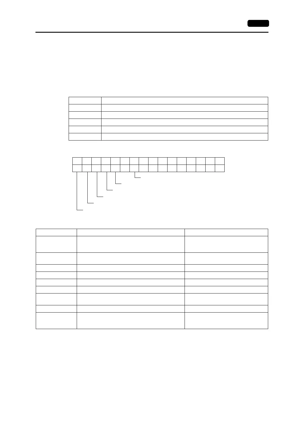
• $s730-761
The following status code for the PLC connected at the MJ port is stored.
Errors other than the above are stored as shown below.
Solution
1. Check the parameter setting of the PLC connected at the MJ port and the setting in the [Temp.
CTRL/PLC2Way Comm. Setting] dialog.
2. Check the cable connection.
3. Data may be disrupted because of noise. Fix noise.
* If you still cannot solve the error even after following the suggestions above, contact your local
distributor.
Code Contents
0000H Normal
FFFFH Timeout
8001H Check code error
8002H Data error
800BH Error code received from the PLC connected at the MJ port
Buffer-full error
Parity error
Overrun error
Framing error
Break detection
1514131211109876543210
0 000000000
MSB LSB
Error
0: Bits 0 to 14 are all “0.”
1: Any bit 0 to 14 is not “0.”
Error Details Solution
Timeout
Although a request to send is given to the PLC connected
at the MJ port, no answer is returned within the specified
time.
Check 1, 2, 3 described below.
Check code error
The check code in the PLC connected at the MJ port
response was not correct.
Check 1, 3 described below.
Data error The code of the received data is invalid. Check 1, 2, 3 described below.
Error code received An error occurs at the PLC connected at the MJ port. Refer to the instruction manual for the PLC.
Buffer full The V7 buffer is full. Contact your local distributor.
Parity An error occurred in parity check. Check 2, 3 described below.
Overrun
After one character is received, the next character is
received before internal processing is completed.
Check 1, 3 described below.
Framing Although the stop bit must be [1], it is detected as [0]. Check 1, 2, 3 described below.
Break detection
SD (TXD) of the PLC connected at the MJ port remains at
the low level.
Examine the connection between SD (TXD)
of the PLC connected at the MJ port and RD
(RXD) of the V7 series.