Appendix 3 n : 1 Connection (Multi-link) App3-3
For V706:
For V706 + DU-01, refer to “For V7 Series:” above.
Since MJ2 is adapted to 4-wire connection, it is necessary to change the signal connection from 4-wire
to 2-wire for multi-link 2 connection.
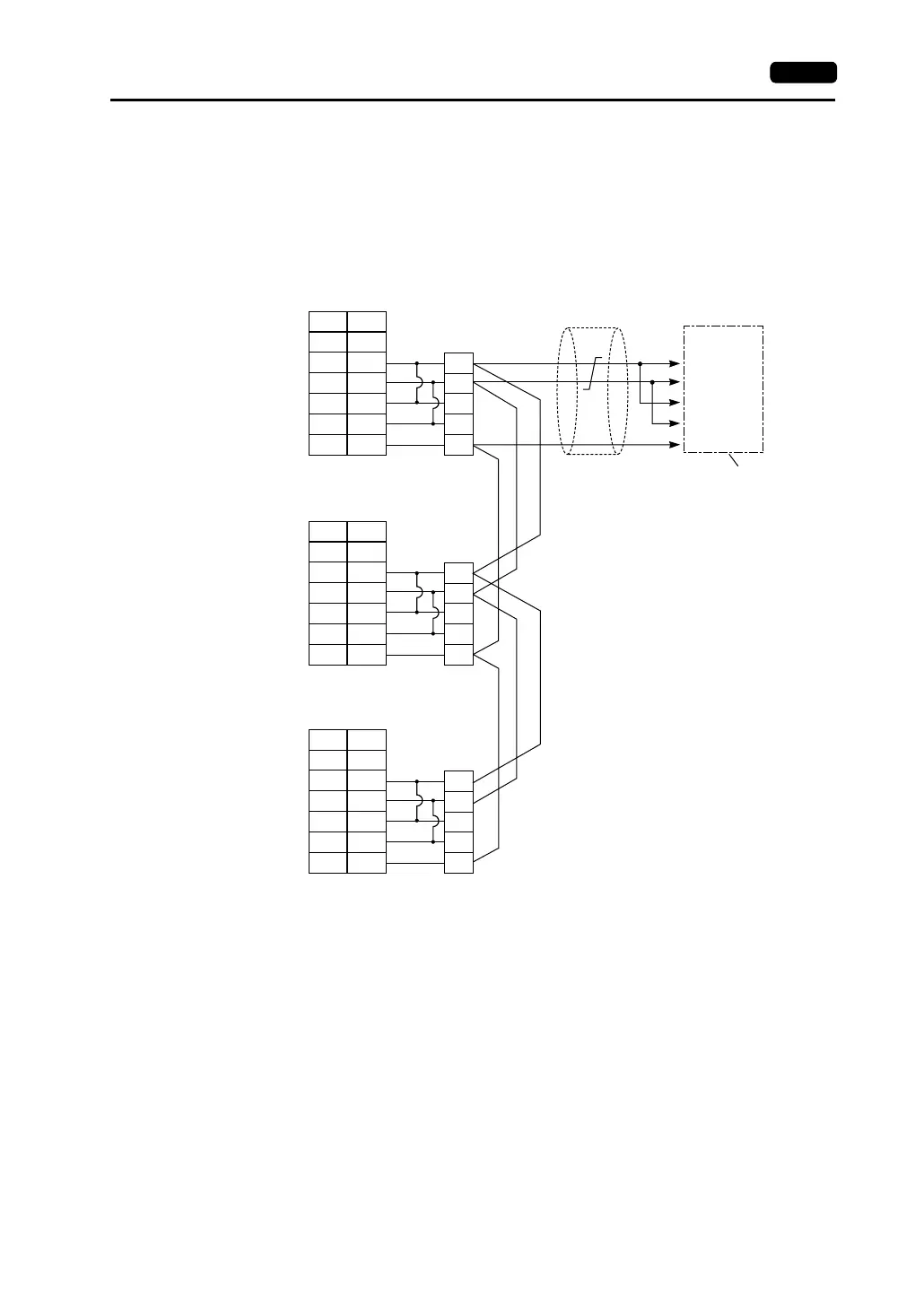
When a jumper is required on the PLC:
SG
+SD
-SD
+RD
-RD
5
1
2
7
8
SHELL
SG
+SD
-SD
+RD
-RD
SG
+SD
-SD
+RD
-RD
5
1
2
7
8
SHELL
SG
+SD
-SD
+RD
-RD
SG
+SD
-SD
+RD
-RD
5
1
2
7
8
SHELL
SG
+SD
-SD
+RD
-RD
SG
Terminating resistance
(OFF)
Shield
To the PLC’s RS-422
port of the link unit
Receive data (+)
Receive data (−)
Send data (+)
Send data (−)
Terminating resistance
(ON)
Terminating resistance
(OFF)
Terminating resistance
(ON)
Signal
Name
Pin No.
V706
MJ2
* Slide the slide switch on the V706 to the lower position for RS-422.
*
Pin No.
V706
MJ2
*
Pin No.
V706
MJ2
*
Signal
Name
Signal
Name