App6-6 Appendix 6 Universal Serial Communications
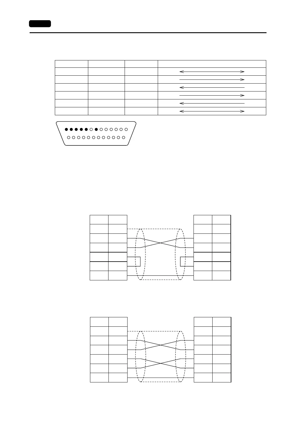
CN1: RS-232C Connector Specifications
The specifications for the RS-232C connector that links to the communication device are shown below.
• FG signal
- Connect the shielded cable to Pin No. 1 on the V series side. When there are FG terminals on
both the communication device and the V series, connect the shielded cable to one of the FG
terminals.
- If both of the terminals are connected, problems such as noise might result in abnormal data
transmission.
• Wiring
Perform wiring as shown below.
<Executing Flow Control>
Pin No. Name Signal Name Signal Direction (V Series ←→ Communication Device)
1 Frame ground FG
2 Send data SD
3 Receive data RD
4 Request to send RS
5 Clear to send CS
7 Signal ground SG
1 2 3 4 5 6 7 8 9 10 11 12 13
14 15 16 17 18 19 20 21 22 23 24 25
* Contact arrangement of the pin insert
FG
SD
RD
RS
CS
SG
1
2
3
4
5
7
FG
SD
RD
RS
CS
SG
1
2
3
4
5
7
* Use twist-shielded cables.
V series (CN1)
General-purpose
computer
Signal
Name
Pin No.
Signal
Name
Pin No.
FG
SD
RD
RS
CS
SG
1
2
3
4
5
7
FG
SD
RD
RS
CS
SG
1
2
3
4
5
7
* Use twist-shielded cables.
V series (CN1)
eneral-purpose
computer
Signal
Name
Pin No.
Signal
Name
Pin No.