App6-20 Appendix 6 Universal Serial Communications
• Interrupt
There are five interrupt settings:
Switch ON interrupt
Switch OFF interrupt
Keypad interrupt
Screen interrupt
Macro: OUT_ENQ
For details, refer to page App6-38.
• Execute Flow Control (disabled for V706)
Check the [Execute Flow Control] when interrupt from V series is needed to be prohibited. (e.g.
when the host cannot receive interrupt data)
The action when you check the [Execute Flow Control] is shown below.
- When CS (pin 4) on V series side is ON:
Interruption is output.
- When CS (pin 4) on V series side is OFF:
Interruption is not output.
When CS is ON, interruption information stored by then is output in succession.
(Interruption information for 3 times can be stored at the most.)
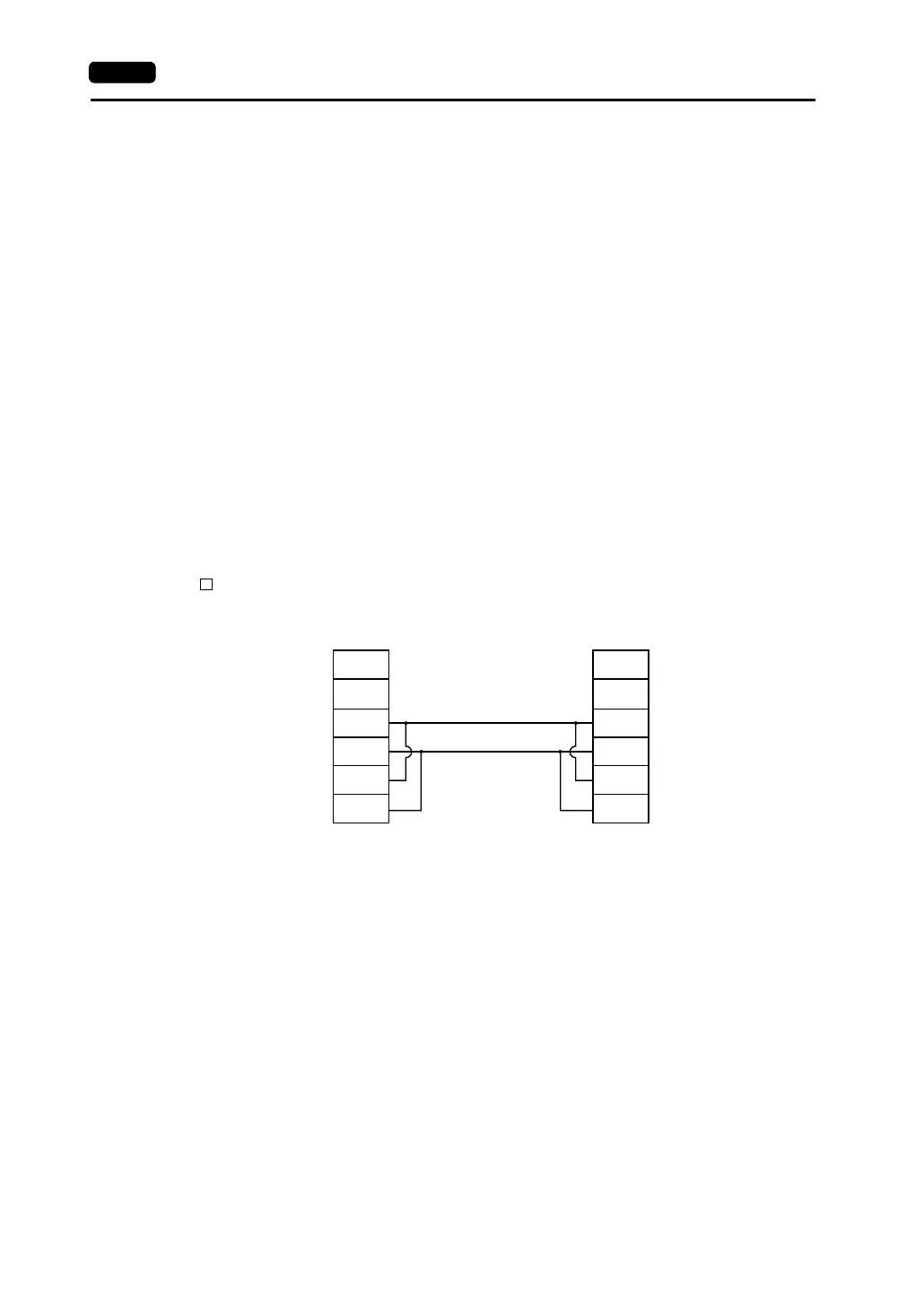
• Execute 4 Wire Control
This setting is available only for 1 : 1 communication with RS-422 using four-wire.
Normally, V series uses the same cables to send or receive data. (See the diagram below.) For
this reason, send output remains OFF (High impedance) except for sending signals from V series.
However, depending on the host specifications, four-wire control must be used without the send
output OFF from the V series. In this case, you must select four-wire processing and check the
[ Execute 4 Wire Control].
• Connection
Set the connection method for the V series and host.
1 : 1 ........... There is one V series machine and one host.
1 : n ........... Multiple V series units are connected to one host.
• Local Station Number
When multiple V series machines are connected to one host, set a station number for each V
series.
• Parity
None
Odd
Even
• Send Delay Time
Set the time for V series to send a response to a host after receiving a command from a host.
• Busy Time
For details, refer to page App6-29.
• Trans. Mode
Set whether or not there should be a CR/LF or sum check at the end of transmission data.
FG
+SD
−SD
+RD
−RD
FG
RDA
RDB
SDA
SDB
V series (CN1) Host
Signal
Name
Signal
Name
<2-wire system>