Appendix 7 V-Link App7-3
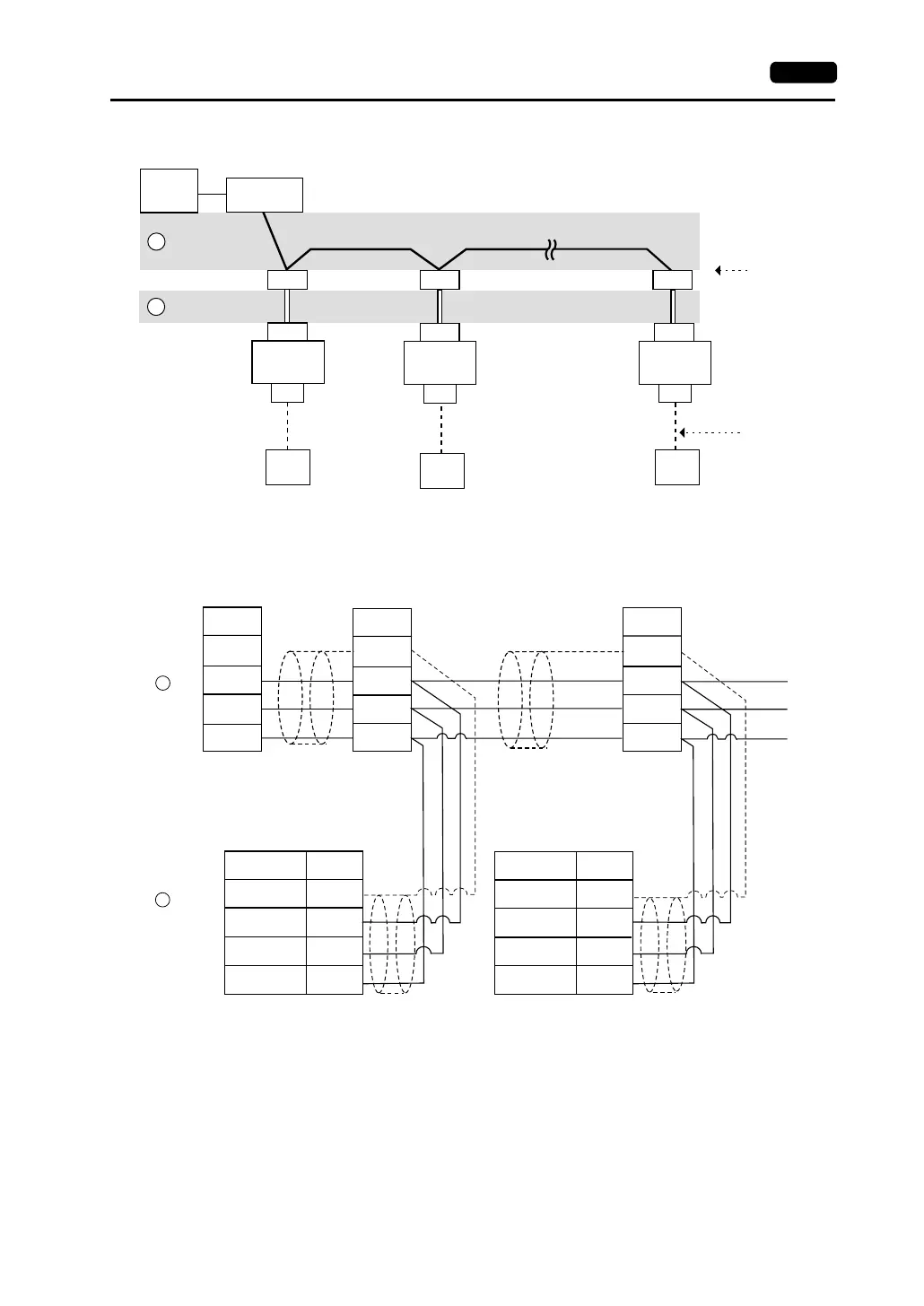
RS-485 (V7 series: maximum 31 sets)
Wiring example of above (a) and (b)
CN1
CN1
CN1
MJ2/1
MJ2/1 MJ2/1
a
b
V6-TMP
RS-232C
RS-422
RS-485
PLC
PLC
PLC
}
RS-485
}
*
}
*
}
*
Computer
V7
Local Port 1
V7
Local Port 2
V7
Local Port 31
RS-232C →
RS-485
conversion
Terminal block Terminal block Terminal block
* 0.5 m recommended (1.0 m maximum)
+
1
+
−
RS-485
−
2
+
1
−
2
+
−
+
−
a
b
SG
5
SG
5
SG
SG
SG
FG
FG
FG
*1 *1
Signal Name
V7 series
Modular jack, 8-pin
Pin No.
(Black)
(Green)
V7 series
Modular jack, 8-pin
Signal
Name
Signal
Name
Signal
Name
(Black)
(Green)
Terminal
block
Terminal
block
Signal Name Pin No.
*1 V6-TMP is connected to FG
when the V7 series is used and
to SG when the V706 is used.