3. Automationdirect PLC 3-3
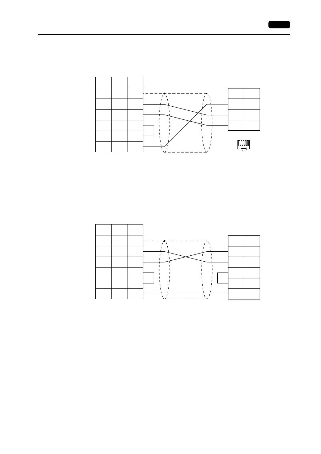
Wiring Diagram 2
Wiring Diagram 3
SG
PLC
RxD
TxD
1
3
4
654321
1
2
3
4
5
7
SD
RD
RS
CS
SG
SHELL
8
7
5
*1
* Use shielded twist-pair cables.
Modular connector 6-pin
D-sub 25-pin (male)RJ-45 8-pin
V Series
CN1
V706
MJ2
*1 Pin No. 1 of CN1 is used
as FG.
The metal shell of the
modular jack 2 on the
V706 is used as SG.
Signal
Name
Pin No. Pin No.
Signal
Name
Pin No.
TXD
RXD
PLC
RTS
CTS
0V
2
3
4
5
7
1
2
3
4
5
7
SD
RD
RS
CS
SG
SHELL
8
7
5
*1
* Use shielded twist-pair cables.
High density D-sub 15-pin (male)
D-sub 25-pin (male)RJ-45 8-pin
V Series
CN1
V706
MJ2
*1 Pin No. 1 of CN1 is used
as FG.
The metal shell of the
modular jack 2 on the
V706 is used as SG.
Signal
Name
Pin No. Pin No.
Signal
Name
Pin No.