13. KOYO ELECTRONICS PLC 13-7
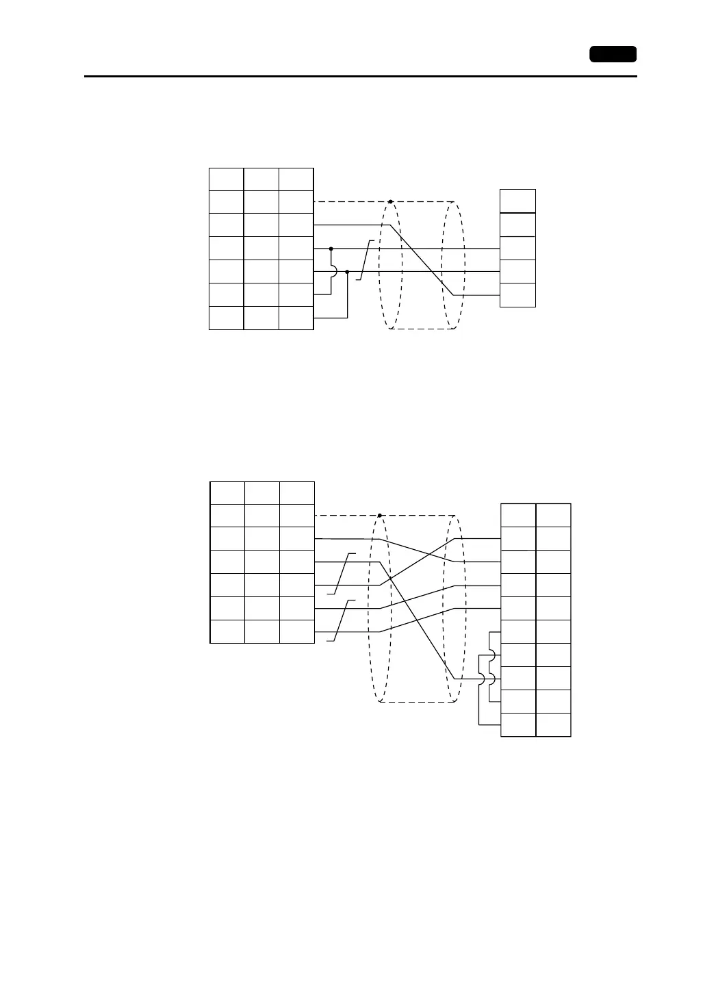
Wiring Diagram 5
Wiring Diagram 6
T1
T2
PLC
T3
FG
1
7
12
13
24
25
SG
+SD
-SD
+RD
-RD
5
1
2
7
8
SHELL
*1
* Use shielded twist-pair cables.
D-sub 25-pin (male)RJ-45 8-pin
V Series
CN1
V706
MJ2
*1 Pin No. 1 of CN1 is used
as FG.
The metal shell of the
modular jack 2 on the
V706 is used as SG.
Signal
Name
Pin No. Pin No.
Signal
Name
0V
TXD+
PLC
TXD−
RTS+
RTS−
RXD+
CTS+
CTS−
7
9
10
11
12
13
14
15
RXD− 6
1
7
12
13
24
25
SG
+SD
-SD
+RD
-RD
5
1
2
7
8
SHELL
*1
* Use shielded twist-pair cables.
High-density D-sub 15-pin (male)
D-sub 25-pin (male)RJ-45 8-pin
V Series
CN1
V706
MJ2
*1 Pin No. 1 of CN1 is used
as FG.
The metal shell of the
modular jack 2 on the
V706 is used as SG.
Signal
Name
Pin No. Pin No.
Signal
Name
Pin No.