Modules and transducers
QuantumX A03031_24_E00_01 HBM: public 113
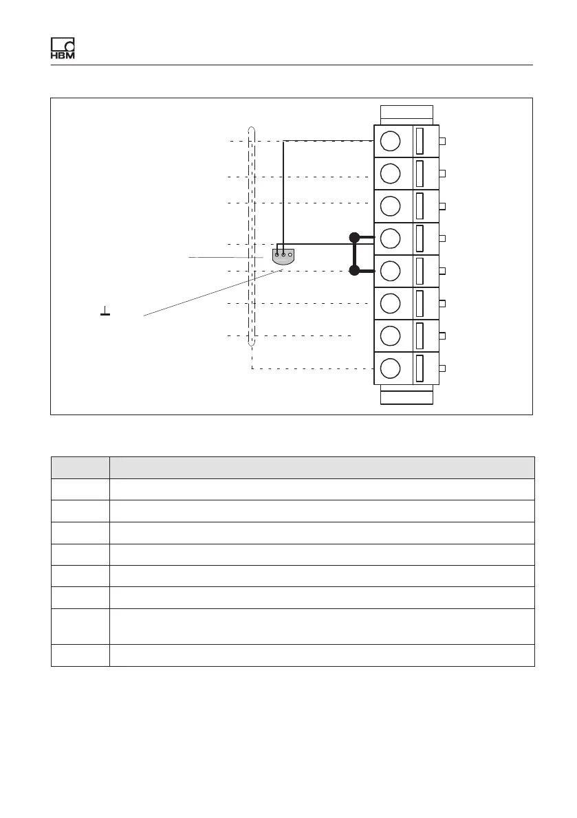
1
2
3
4
5
6
7
8
12
3
1‐wire EEPROM
(Maxim DS24B33+)
view from below
Bridge
1
2 Data
3 No function
Fig. 8.18 Pin arrangement of connection plug, view from the connection side
Pin Connector
1 TEDS (+)
2 Bridge excitation voltage (+)
3 Sense lead (+)
4 Bridge excitation voltage (-), (TEDS) (-)
5 Sense lead (-)
6 Measurement signal (+), voltage input 10 V / 30 V (+)
7 Measurement signal (-), voltage input 0 V / 10 V (-), bridge excitation
voltage (+) for quarter bridges
8 Housing (shield connection)