4.20 Bed Surface Air System Assembly
Chapter 4: Removal, Replacement, and Adjustment Procedures
Page 4 - 52 Affinity® Three Birthing Bed and Affinity® Four Birthing Bed
Service Manual (MAN272 REV 4)
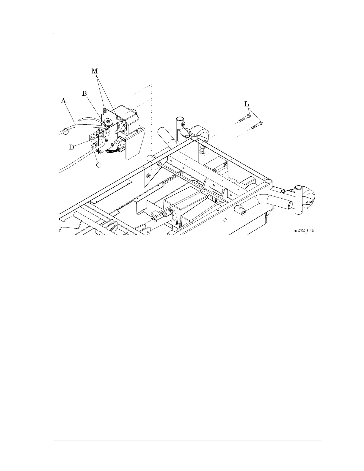
Figure 4-26. Bed Surface Air System Assembly
10. Disconnect the transformer assembly power cable from air system control
P.C. board (F) connector P19 (E) (see figure 4-27 on page 4-53).
11. Disconnect the cable (G) from logic control P.C. board connector P8 to air
system control P.C. board (F) connector P18 (H).
12. Using the small wire cutters, cut and remove the cable tie (I) that secures
the linear pump power cable (J), air system power cable, and air system
control P.C. board cable (G) to the mounting bracket (K).
13. Using the two ½" wrenches, remove the bolts (L) and nuts (M) that secure
the air system to the bed frame (see figure 4-26 on page 4-52).
14. Remove the air system from the bed.