4.23 Logic Control P.C. Board Assembly
Chapter 4: Removal, Replacement, and Adjustment Procedures
Page 4 - 58 Affinity® Three Birthing Bed and Affinity® Four Birthing Bed
Service Manual (MAN272 REV 4)
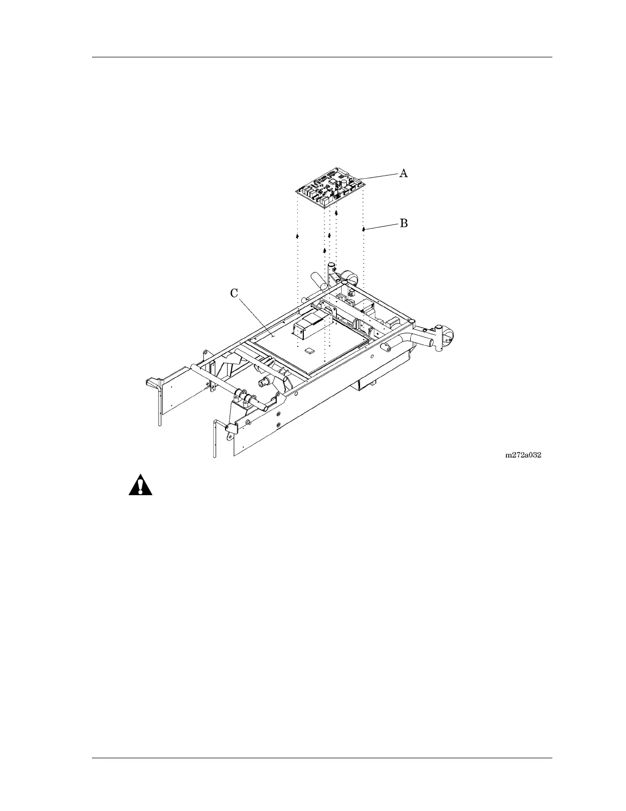
8. Using the needle nose pliers, compress the locking tabs on the five logic
control P.C. board mounting standoffs (B), pulling the logic control P.C.
board (A) slightly up and over the locking tab on each mounting standoff.
Figure 4-30. Logic Control P.C. Board Assembly
For shipping and storage, place the removed P.C. board in an antistatic
protective bag. Failure to do so could result in equipment damage.
9. Handling the logic control P.C. board (A) by its edges with clean hands,
maneuver and remove it from the electronics plate weldment (C).
a. If replacing a 65345 logic control P.C. board and 67208 interface P.C.
board, discard them.
b. If replacing a 68121 logic control P.C. board, place it in an antistatic
protective bag.
Modifying the Lockout Switch Cable
When replacing a 65345 logic control P.C. board and 67208 interface P.C.
board with a 68121 logic control P.C. board, the lockout switch cable must be
modified as follows: