4.23 Logic Control P.C. Board Assembly
Chapter 4: Removal, Replacement, and Adjustment Procedures
Affinity® Three Birthing Bed and Affinity® Four Birthing Bed Page 4 - 59
Service Manual (MAN272 REV 4)
4
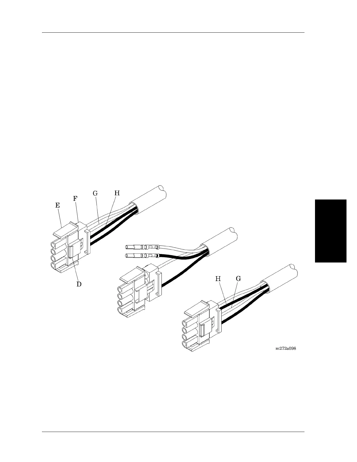
1. Locate the P3 connector of the lockout switch cable. When used with a
65345 logic control P.C. board and 67208 interface P.C. board, the order of
the four wires in the connector housing is red, red adjacent, and black,
black adjacent (see figure 4-31 on page 4-59). Pin 1 may be either red or
black.
If the order of the four wires in the connector housing is red, black, red, black
alternating, the lockout switch cable has already been modified for use with a
68121 logic control P.C. board. Skip to “Replacement” on page 60.
2. Using the needle nose pliers, compress the locking tabs (D) holding the
connector shell (E) and the backshell (F) of the plastic connector housing
together, and pull the two shells about ¼" apart. This procedure unlocks the
pins in the housing.
Figure 4-31. Lockout Switch Cable P3 Connector
3. Pull the red middle wire (G) with its attached pin, and the black middle
wire (H) with its attached pin, out of the backshell (F).
4. Reverse the order of the two middle wires and pins, and reinstall them into
the backshell, pushing on each wire until you hear a click and the pin is
seated tightly. The order of the four wires in the connector housing should
now be red, black, red, black alternating, for use with a 68121 logic control
P.C. board. Pin 1 may be either red or black.