4.23 Logic Control P.C. Board Assembly
Chapter 4: Removal, Replacement, and Adjustment Procedures
Page 4 - 60 Affinity® Three Birthing Bed and Affinity® Four Birthing Bed
Service Manual (MAN272 REV 4)
5. Push the connector shell (E) and the backshell (F) together until you hear a
click and the locking tabs (D) are locked, holding the two parts of the
connector housing firmly together.
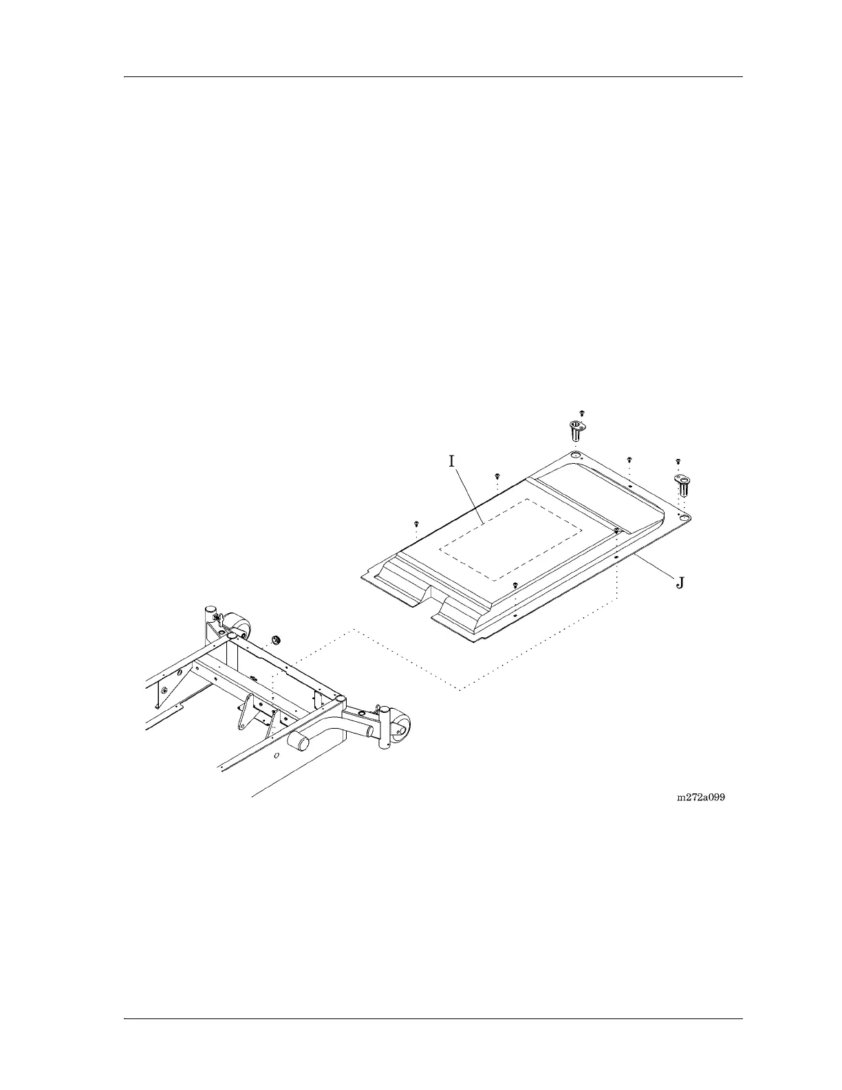
6. Clean the underside of the top motor cover with a cloth soaked in isopropyl
alcohol, remove the protective backing from the 6399301 wiring diagram
(I), and install the new wiring diagram in place of the existing wiring
diagram located on the underside of the top motor cover (J) (see figure 4-
32 on page 4-60).
It is not necessary to remove the old wiring diagram, as long as the new one
covers it completely.
Figure 4-32. Logic Control P.C. Board Wiring Diagram
Replacement
1. To install the replacement logic control P.C. board (A), reverse the removal
procedures, finishing with the battery cable connection P5.
2. Ensure that the wiring connectors are firmly connected to the logic control
P.C. board (A) receptacles.
3. Do the “Function Checks” on page 2-4.