4.3 Hilow Drive Motor Assembly
Chapter 4: Removal, Replacement, and Adjustment Procedures
Page 4 - 8 Affinity® Three Birthing Bed and Affinity® Four Birthing Bed
Service Manual (MAN272 REV 4)
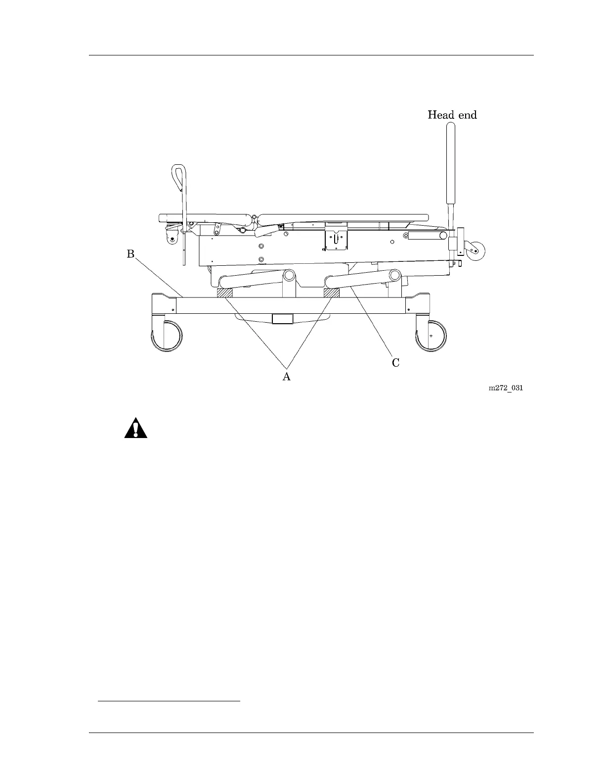
Figure 4-3. Bed Support Location
Ensure that the night light is not damaged when the bed is being
lowered. Failure to do so could result in equipment damage.
10. Deactivate the lockout function, and lower the bed until both lift arms (C)
are resting on the 2" x 4"s.
11. Using a ratchet and T25 Torx®
1
head bit, remove the four screws (D)
securing the electronics plate weldment (E) to the bed frame (see figure 4-4
on page 4-9).
12. To improve access to the hilow drive motor assembly (F) on the right side,
carefully lift and move the electronics plate weldment (E) to the patient’s
left-hand side of the bed.
13. Unplug the hilow drive motor assembly (F) power cable (G) from logic
control P.C. board (H) connector P15.
1. Torx® is a registered trademark of Textron, Inc.