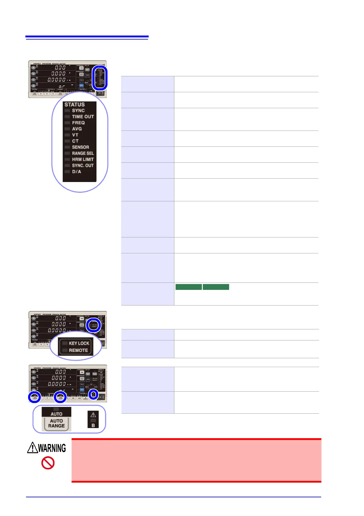
These lamps indicate the setting status.
Function lamps light up when set to a value other than the default setting.
SYNC
Lights up when the synchronization source is set to I or DC
(the default setting is voltage: U). (p.48)
TIME OUT
Lights up when the synchronization detection timeout is set
to 1 sec. or 10 sec. (the default setting is 0.1 sec.). (p.54)
FREQ
Lights up when the zero-cross and frequency measure-
ment filter setting is set to 100 Hz, 5 kHz, or 100 kHz (the
default setting is 500 Hz). (p.50)
AVG
Lights up when the number of averaging iterations is set to
a value other than the default value of 1. (p.56)
VT
Lights up when the VT ratio setting is set to a value other
than the default setting of 1. (p.58)
CT
Lights up when the CT ratio setting is set to a value other
than the default setting of 1. (p.58)
SENSOR
Lights up when the current input method setting is set to
TYPE.1 or TYPE.2 (current sensor input) (the default set-
ting is OFF [current value direct input]). (p.38)
RANGE SEL
Lights up when either the voltage measurement range or
current measurement range is set to OFF. (the default set-
ting is range select: ON). (p.46)
Lights up when any of the zero-cross threshold levels is set
to a value other than the default setting of 1%. (p.52)
HRM LIMIT
Lights up when the harmonic analysis order upper limit is
set to a value other than the default value of 50. (p.76)
SYNC. OUT
Lights up when the synchronized measurement I/O setting
is set to OUT (Master). Flashes with external synchronized
signal input when set to IN (Slave). Turns off when set to
OFF. (p.78)
D/A Lights up when the 7 channels of D/A output are set to val-
ues other than their default values. (p.88)
surement lines.