1.3 Names and Functions of Parts
17
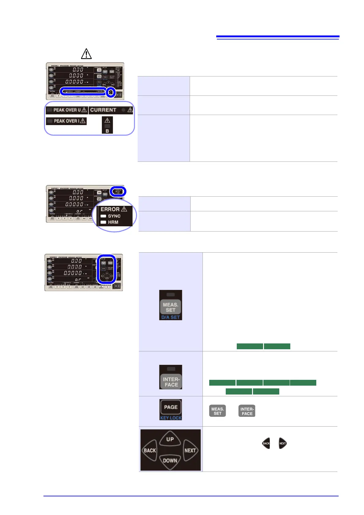
Warning indicator lamps
Error indicator lamps
Function setting keys and indicator lamps
The following warning lamps are lit up when there is a hazard or the instrument is
unable to perform measurement accurately:
PEAK OVER U
Lights up when an overvoltage input warning occurs, indicat-
ing that the input voltage peak value has exceeded ±1,500 V
or ±600% of the voltage measurement range.
PEAK OVER I
Lights up when an overcurrent input warning occurs, indicat-
ing that the input current peak value has exceeded ±100 A
or ±600% of the current measurement range.
CURRENT ●
Instrument protection mode. Flash when if current of greater
than or equal to ±612 mA peak is inputted continuously for
10 or more seconds when using a range from 1 mA to 100
mA with fixed range.
If you attempt to switch from one of the 200 mA to 20 A rang-
es to one of the 1 mA to 100 mA ranges while a current of
±612 mA peak or greater is being input, you will not be able
to switch ranges, and the indicator will flash.
The following error lamps are lit up when the instrument is unable to perform mea-
surement accurately:
SYNC
Lights up when a synchronization error occurs, indicating
that synchronization cannot be detected. (p.48)
HRM
Lights up when a harmonic measurement synchronization
error occurs, indicating that the harmonic measurement syn-
chronization frequency range was exceeded. (p.71)
MEAS. SET
The lamp will light up if pressed when the following set-
tings are being configured:
• Synchronization source
• Current input method
• Range select
•CT ratio
•VT ratio
• Frequency measurement range (zero-cross filter)
• Synchronization detection timeout
• Integration time, auto-range integration
• Number of averaging iterations
• Harmonic analysis upper limit order
• Synchronized measurement I/O (master, slave)
• D/A output
INTERFACE
The lamp will light up if pressed when setting the inter-
face.
•LAN
• RS-232C
•GP-IB
• Used to switch among settings configured with
and .
• Used with the key lock function.
Used to move among and select settings.
• Pressing and holding or will cause the flash-
ing setting to move successively.
PW3335 PW3335-02 PW3335-03 PW3335-04