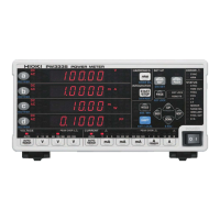
1.3 Names and Functions of Parts
18
*D/A OUTPUT terminals
The following voltages are output from each terminal.
Level output: Level (analog) output is updated at an interval of approximately 200 ms.
High-speed level output: The active power for every cycle for the voltage or current set as the synchronization source is
output.
Waveform output: The input waveform as sampled at a frequency of approximately 700 kHz is output.
Power Inlet
Connect the supplied
power cord. (p.33)
Model name number
Current input terminal ( I )
Input current signals. (p.26)
Voltage input terminal (U )
Input voltage signals. (p.26)
Example: PW3335-04
External control terminal
(EXT. CONTROL)
Input signals from an integration
external control function. (p.82)
D/A Output terminal
*
(D/A OUTPUT)
The voltages listed below
are output from each
terminal. (p.85)
External current sensor
input terminal
(CURRENT SENSOR)
Connect the optional current
sensors. (p.100)
Manufacturer's Serial No.
Do not remove this label, as it is
required for product support.
MAC address
of the LAN
RS-232C connector
Connect a communica-
tions cable when using
the RS-232C interface.
(p.123)
GP-IB connector
Connect a communica-
tions cable when using the
GP-IB interface. (p.127)
LAN connector
Connect a communica-
tions cable when using the
LAN interface. (p.116)
External synchronization terminal
(EXT. SYNC)
Connect a cable for synchronized
measurement. (p.78)
Rear
Terminal Default setting Description
DA1 V : AC+DC, STD.2 Each D/A output terminal can be set to any of the following:
• Level output
• High-speed level output
• Waveform output
See:
Appendix 2 Detailed Specifications of Output (p. A2)
DA2 A : AC+DC, STD.2
DA3 W : AC+DC, STD.2
DA4 PF : AC+DC, STD.2
DA5 V : AC+DC, FASt
DA6 A : AC+DC, FASt
DA7 W : AC+DC, FASt

 Loading...