2.2 Connecting the Measurement Lines
31
Example 2: Input voltage of 3.3 V DC, current of 28 A DC, and active power of 92.4 W DC
Method 1:
Since the input current is 28 A DC, the 20 A range (with an effective measurement range of 0.2 A to 30 A)
will be used.
Instrument loss = (Input current)
2
× (Current input resistance)
= (28 A)
2
× 15 m = 11.76 W
Method 2:
Instrument loss = (Input voltage)
2
÷ (Voltage input resistance)
= (3.3 V)
2
÷ 2 M = 0.000005445 W
Connect the instrument using Method 2, which has the lower instrument loss. The instrument loss in this
configuration is 0.000005445 W.
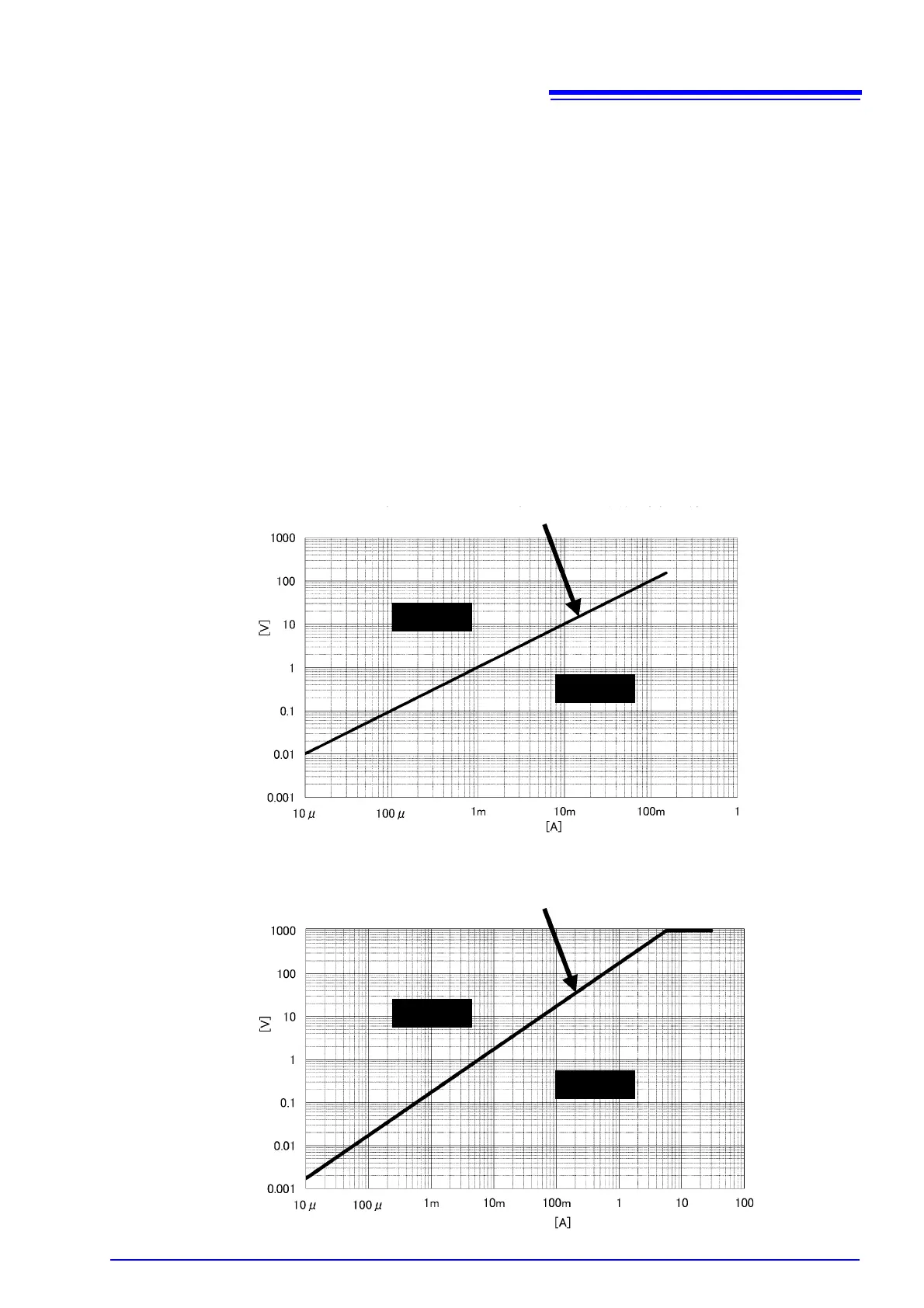
The following figure provides some guidelines for choosing the connection method. The horizontal axis rep-
resents input current, and the vertical axis represents input voltage. The straight line on the graph indicates
values for which the loss caused by the input resistance of the voltage inputs is equal to the loss caused by
the input resistance of the current inputs. Using this line as a boundary, chose Method 1 when the input falls
in the area above and to the left of the line, and choose Method 2 when the input falls in the area below and
to the right of the line. For example, if the input voltage is 100 V, you would use an input current of 600 mA
(in fact, 577.4 mA) as the boundary, choosing Method 1 for currents of less than approximately 600 mA and
Method 2 for currents of greater than approximately 600 mA.
Line at which voltage input loss equals current input loss (boundary line)
Input voltage
Input current
Method 1
Method 2
Current input resistance: 520 mΩ
Line at which voltage input loss equals current input loss (boundary line)
Current input resistance: 15 mΩ
Method 1
Method 2
Input voltage
Input current

 Loading...


