18
Names and Functions of Parts
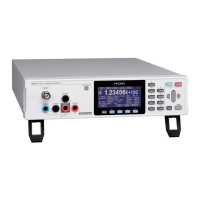
1.2 Names and Functions of Parts
Front
Operation keys (p. 21)
Measurement terminals
Connect measurement leads to
these terminals.
See p. 11.
1
HIGH VOLTAGE LED
Lights up while a high voltage
is output.
Screen
Monochrome graphic LCD
2 43 5
The model illustrated below is
Model SM7120.
Measurement
terminal
Description
1
INPUT
This is a measurement input terminal.
Has triaxial structure. The central conductor is for measurement input. The second-
outermost electrode is connected with the GUARD terminal. The second-outermost
electrode is connected with the GROUND terminal.
Additionally installing the shield
wires in the measurement
line enables the instrument to
perform stable measurement
with no inuence of exogenous
noise.
Electromagnetic shielding wire
Guard wire for
measurement
Measurement input wire
2
GUARD
This is a guard terminal.
It is the common side of the ammeter.
Used in order to take the guard that cancels the eect of the a leakage current owing
through the retainer, measurement xture, etc. of the measured object.
The GUARD terminal has a negative (−) electrical polarity.
3
GROUND
This is a ground terminal.
Used to reduce the eects of noise and minimize the risk of an electric shock.
Usually connected to the OUTPUT terminal or the GUARD terminal with the shorting
plug.
4
OUTPUT
This is a voltage output terminal.
Insulation resistance is measured between this OUTPUT terminal and the INPUT
terminal.
The electrical polarity of the OUTPUT terminal is positive (+).
 Loading...


