Shenzhen Hpmont Technology Co., Ltd. Chapter 6 Function Introduction
HD5L-PLUS Series User Manual V1.0 65
Ref. Code
Function Description Setting Range [Default]
5: Contactor output control.
• To open/close the output contactor.
6: Brake output control.
• To open/close the brake.
7, 8: Speed level detection signal 1, 2 (FDT1, FDT2).
• Refer to F05.12 - F05.13.
9: Speed arrival signal (FAR).
• The indication signal will output when the output speed of HD5L-PLUS is within the FAR range. The
detect range is set by F05.16 (speed arrival FAR range).
• The indication signal will also output at stop.
10: Up signal output.
• ON signal will output when the elevator is at up running.
11: Down signal output.
• ON signal will output when the elevator is at down running.
12: Under-voltage.
• ON signal will output when HD5L-PLUS is in under-voltage status.
13: Unused.
14: Controller fault.
• ON signal will output when HD5L-PLUS has fault.
15: Elevator stop signal.
• When the elevator stops, HD5L-PLUS will stop and outputs 2s pulse signal, according to which HD5L-
PLUS revokes run command.
16 - 19: Unused.
20: Speed outputs.
21: Advanced door open signal output.
• When the elevator reference speed < F20.11 (pre-open door running speed threshold), the pre-
opening door signal output is valid. When the elevator stops, after the delay of F20.12, the pre-opening
door signal output becomes invalid.
After the elevator is restarted, the early opening signal is invalid.
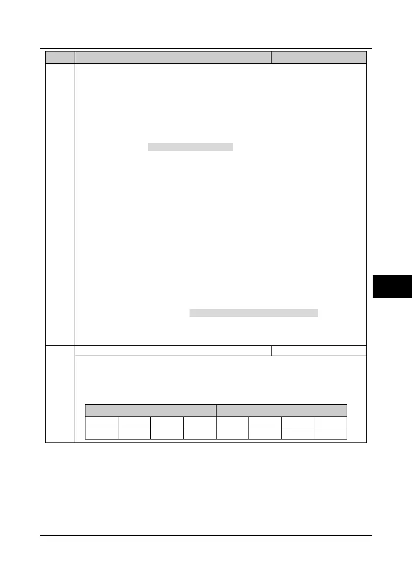
Output terminal logic setting
See the table below for the corresponding output terminal of each bit (binary).
• 0: Positive logic. When output terminals are connected to common port, this logic is enabled. Otherwise
the logic is disabled.
• 1: Negative logic. When output terminals are connected to common port, this logic is disabled. Otherwise
the logic is enabled.
Ten Unit
Bit7 Bit6 Bit5 Bit4 Bit3 Bit2 Bit1 Bit0
- - Y4 (R LY ) Y3 Y2 Y1 DO2 DO1
 Loading...
