CHAPTER 2
2-6 IEN HARDWARE REFERENCE 940043-002
Front Panel
The IEN 1000 chassis is a single port frame relay access device (FRAD) controller capable of
interfacing with multiple protocols. Each interface status is presented on the front panel in
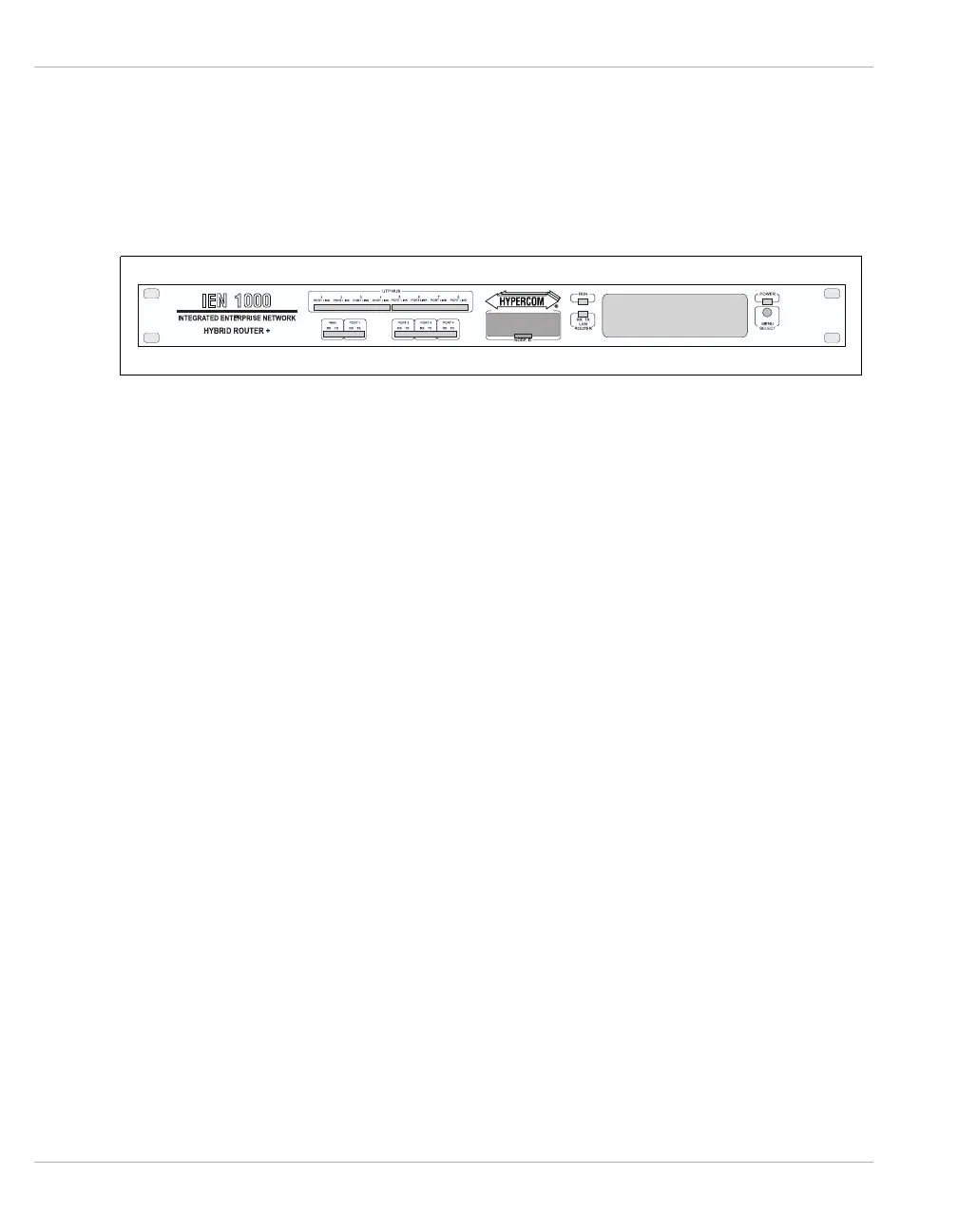
the form of LED indicators and a two-line by 20-character display. Figure 2-1 illustrates the
front panel of the IEN 1000 chassis.
Figure 2-1 IEN 1000 Front Panel
WAN/Port 1 This status window contains LED indicators for the WAN and serial port 1 transmit and
receive status.
Optional
Serial Ports
The Optional Serial Ports contain LED indicators for serial port 2, 3, and 4 transmit and
receive status.
Node ID The Node ID contains four 16-position rotary switches used for configuration and
addressing.
HUB
Interface
The HUB Interface contains LED indicators for the partition and link status of each port on
the HUB08/16 or MAU.
HUB08 Refer to Chapter 3, LET10 for more information about the Ethernet
upgrade module.
MAU08 Refer to Chapter 3, LTR10 for more information about the Token Ring
upgrade module.
RUN Indicator The RUN Indicator contains an LED which flashes to indicate the CPU is running.
LAN Interface The LAN Interface contains LED indicators for the Ethernet or Token Ring LAN interface
transmit and receive status.
Power
Indicator
The Power Indicator contains an LED that indicates power is applied.
Menu Display The Menu Display is a two-line by 20-character display used to provide port status and the
software revision.
Menu Select/
Reset Button
The Menu Select/Reset Button is used to scroll through the Menu Display. Pressing and
holding the Menu Select/Reset Button for five seconds resets the IEN 1000.