CHASSIS
940043-002 INTEGRATED ENTERPRISE NETWORK 2-7
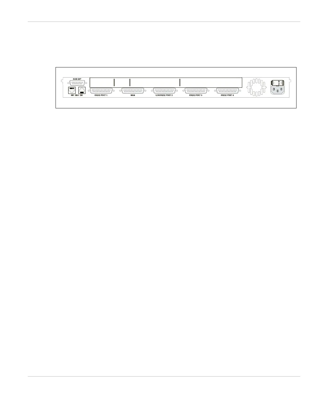
Rear Panel
The rear panel of the IEN 1000 chassis contains connections for a standard default
configuration. Additional interface connections are provided with each add-on component.
Figure 2-2 IEN 1000 Rear Panel
Hub
Expansion
The HUB expansion consists of one DB15 connector used for Ring In and Ring Out
connections when the UTP MAU is installed. Refer to Chapter 3, LTR10 for more
information about the Token Ring upgrade module.
DBU
Connections
The DBU connections consist of one RJ11 port for a 2-wire modem and one RJ45 port for
a 4-wire line interface used with the optional V.32bis DBU Modem. This provides a dial
backup connection.
WAN/Serial
Port 1
Connections
The WAN/Serial Port 1 connections consist of one DB25 RS232/V.35 WAN port and one
DB25 RS232 serial port.
Optional
Serial Ports
The Serial Port connections 2, 3, and 4 consist of one DB25 RS232/V.35 serial port and
two DB25 RS232 serial ports used when the optional CPA03 module is installed. Refer to
Chapter 3, CPA03 for more information about the CPA03 upgrade module.
AC Power
Connector
The AC Power connection consists of one power cord socket with a T5A 250V fuse.