CHASSIS
940043-002 INTEGRATED ENTERPRISE NETWORK 2-9
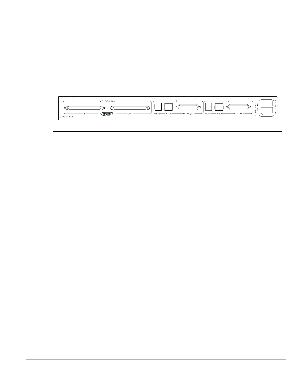
Rear Panel
The rear panel of the IEN 2000 chassis contains the cabling connectors. The two DB25
connectors are used with adapter interfaces or cables to support media, such as RS232,
V.35, Thinnet or AUI Ethernet, and analog voice. Figure 2-4 illustrates the rear panel of the
IEN 2000 chassis.
Figure 2-4 IEN 2000 Rear Panel
The two RJ11 connectors are used with adapter interfaces or cables to support media,
including analog dial, UTP Ethernet, DS1/T1, DDS and ISDN. The two RJ45 connectors
support a standard Token Ring UTP connection.
There are also two bus expansion ports, one labeled IN and one labeled OUT. The bus
expansion ports are used for interconnecting an IEN 2000 with up to three additional IEN
2000 chassis.
Up to four IEN 2000 chassis can be bus connected using a Hypercom Type HB2 cable. Two
chassis are connected by inserting a Type HB2 cable into the OUT port of the first chassis
and into the IN bus expansion port of the second chassis. Use of the IEN 2000 bus
expansion actually extends the backplane, providing a common high-speed, standard and
TDM bus between chassis. Redundant power capabilities are also provided using the Type
HB2 cable.
Ethernet or Token Ring bus extension is required when exceeding the eight port IEN 2000
chassis stack.