SYSTEM CONFIGURATION
940043-002 INTEGRATED ENTERPRISE NETWORK 6-7
IENView Configuration
Following the application of power, the IEN 1000 chassis begins a start-up self-test and
configuration indicated by the menu display. Figure 6-6 illustrates the IEN 1000 menu
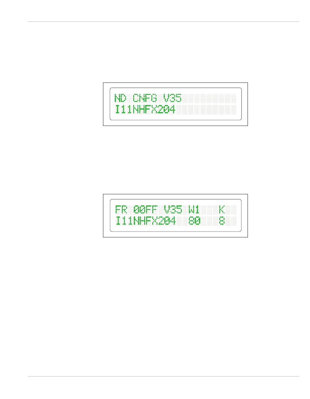
display during a power-on self-test and configuration process.
Figure 6-6 Power-On Self-test and Configuration Display
Successful completion of the start-up self-test is indicated by the RUN indicator flashing.
The menu display and status indicators assume appropriate states following the time period
the respective operating system and communication conditions take to establish connection.
Figure 6-7 illustrates the IEN 1000 menu display after start-up.
Figure 6-7 IEN 1000 Menu Display