4.1 Basic operation
4-1
4. Operation
4.1 Basic operation
An input signal from a master device to the ELECYLINDER triggers operation of the
ELECYLINDER.
The ELECYLINDER status can also be determined when the master device receives signal output
from the ELECYLINDER.
Control is just as simple as when using a solenoid valve (SOL valve) and air cylinder drive.
This manual introduces an example using a PLC connected as the master device.
The ELECYLINDER continues operation while a movement command signal is input,
outputting a position detected signal when the movement is complete.
Turning the movement command signal OFF before the movement is complete interrupts
the operation and causes a gradual stop.
Home return operation is similar.
Reference
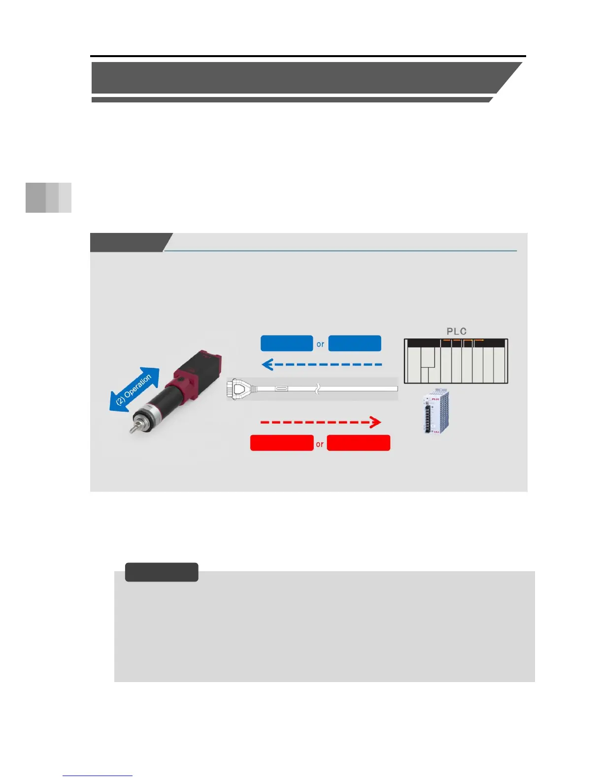
Connection image
Forward
command
Backward
command
Forward end
detection
Backward end
detection
PLC/ELECYLINDER connection
ELECYLINDER
24VDC power supply
(1)
(3)
(1) Input a movement command signal from the PLC. (forward or backward)
(2) The ELECYLINDER operates.
(3) A position detection signal is output from the ELECYLINDER. (forward end or backward end)
Power I/O cable connector

 Loading...


