8.6 How to replace components
8-29
8. Maintenance and Inspection
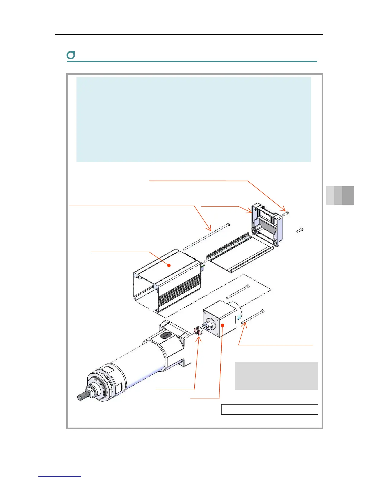
Motor replacement
(1) Loosen the screws and remove the end cover.
(2) Loosen the screws to remove the wiring/connectors, then remove the motor
cover assembly.
→ Refer to "Precautions for connectors/wiring" on page 8-23.
(3) Remove the motor and coupling spacer.
(4) Mount the new motor and coupling spacer.
(5) Return the wiring, connectors and motor cover assembly to their original state.
(6) Attach the end cover.
Rod t
pe replacement method
Motor cover assembly
(controller substrate)
Cross-recessed tapping screws x 2 pcs
(M3 x 10, tightening torque 0.60N・m)
End cover
Hex socket head bolt
R6: 2 pcs, M3 x 50, 0.83N・m
R7: 4 pcs, M4 x 12, 1.76N・m
Motor
Coupling
spacer
Cross-recessed pan screws x 2 pcs
R6/R7: M3 x 110/150, tightening torque 0.60N・m
(M3 x 150/200 for models with brake)
* Hex socket head bolts are used
to fix the motor.
They are not cross-recessed bolts.
(including coupling spacer replacement)

 Loading...


