3.3 Connection arrangement diagram
3-5
3. Wiring
3.3 Connection arrangement diagram
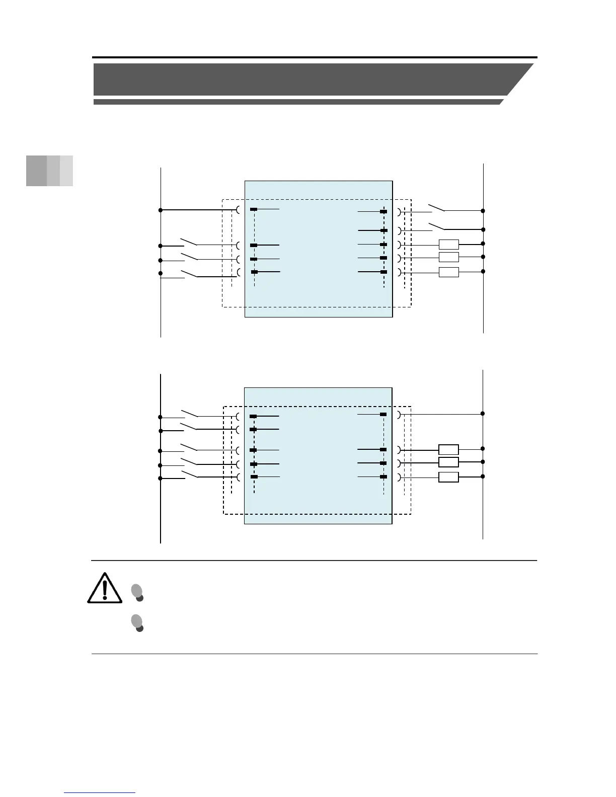
Here the wiring connection method with a power I/O connector is introduced.
Caution
[Note 1] This switch releases the brake forcibly for actuators equipped with a brake.
The switch power capacity requires 24VDC ±10% and 200mA or more.
[*ALM] is a b-contact (active-low) signal.
The output signal is ON in normal conditions and OFF when an alarm occurs.
Note 1
Brake release
[For PNP specification]
ELECYLINDER (NPN specification)
B2
Backward com

 Loading...


