3.4 Wiring connections (for connectors)
3-7
3. Wiring
PLC wiring
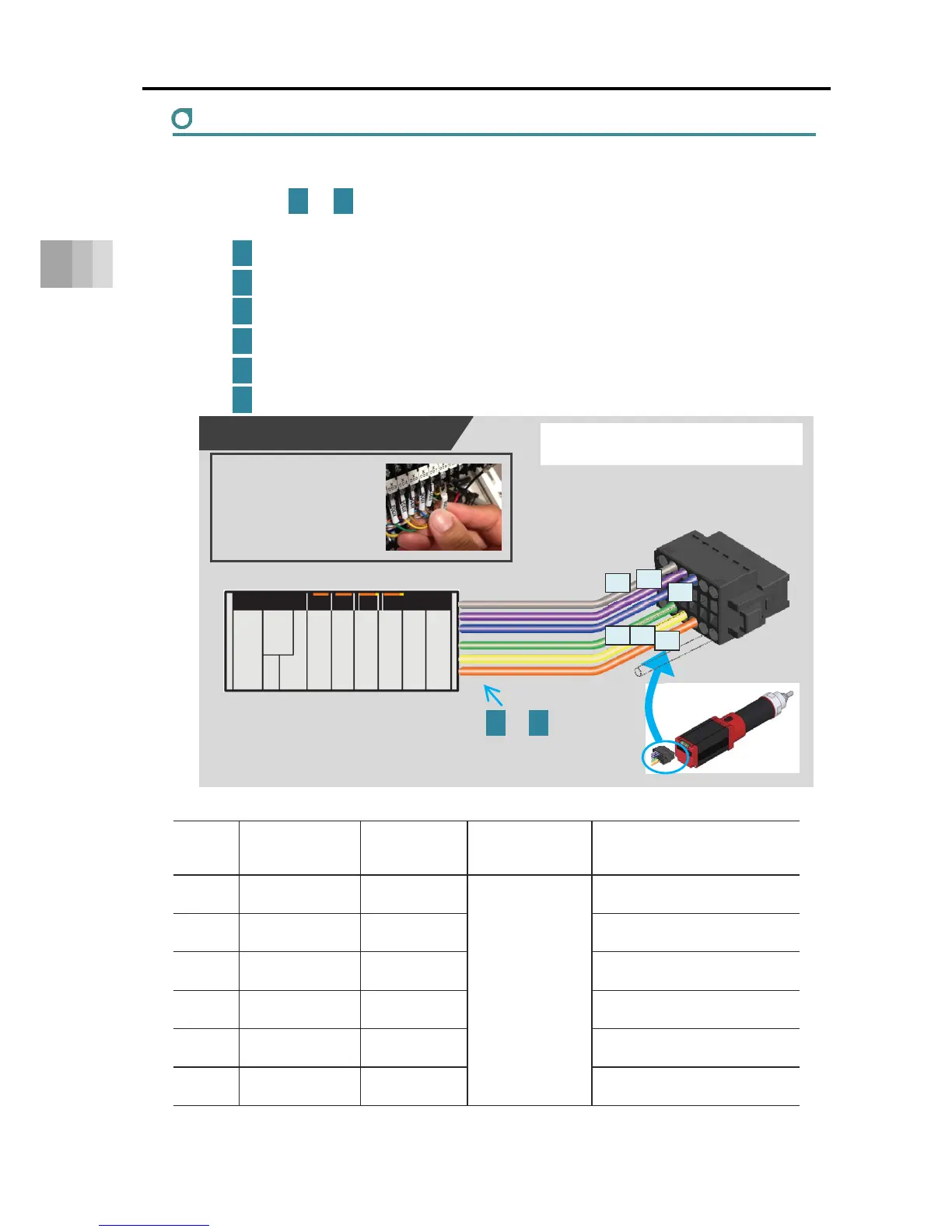
For I/O between the PLC and signals, the signal wiring must be connected to
the connector terminal block.
Connect the to wiring to the connector terminal block while referring to
the connection diagram.
Connect the [B3] connector terminal and the [Backward] output terminal.
Connect the [B4] connector terminal and the [Forward] output terminal.
Connect the [B5] connector terminal and the [Alarm clear] output terminal.
Connect the [A3] connector terminal and the [Backward complete] input terminal.
Connect the [A4] connector terminal and the [Forward complete] input terminal.
Connect the [A5] connector terminal and the [Alarm] input terminal.
Pin
No.
Connector
nameplate
name
Signal
abbreviation
Compatible
wire diameter
Function overview
B3 Backward ST0
KIV 0.20mm
2
(AWG24)
Backward command
B4 Forward ST1 Forward command
B5 Alarm clear RES Alarm clear
A3
Backward
complete
LS0/PE0
Backward complete/
pressing complete
A4
Forward
complete
LS1/PE1
Forward complete/pressing
complete
A5 Alarm * ALM Alarm detection (b-contact)
PLC connection diagram
8
Before starting connector wiring,
check the details on pages 3-8 to 9
A5
A4
A3
B5 B4
B3

 Loading...


