18
INTELLIGENT ACTUATOR
Part 1 Installation
(3) AC-power input connector
A 200-VAC, single-phase or three-phase input connector consisting of six
terminals including motor power terminals, control power terminals and a
PE terminal.
Note) Take note that the single-phase input specification and three-phase
input specification are available depending on the required motor-
drive power source. The standard type only comes with a terminal
block.
Caution To prevent electric shock, do not touch this connector when the
controller is receiving power.
AC Power Connector Specifications
Item Overview Details
Connector
6-pin 2-piece connector by
Phoenix Contact
GMSTB 2.5/6-7.62
Connector name PWR
Connected
unit
Single-phase power source 200/230 VAC, 50/60 Hz
6 PE Protective grounding wire
5INCP_L
200 VAC for control power,
phase L
4INCP_N
200 VAC for control power,
phase N
Cable size
0.75 mm
2
(AWG 18)
3 NC Do not connect this terminal.
2INMP_L
200 VAC for motor power,
phase L
Single-phase specification
Terminal
assignments
1INMP-N
200 VAC for motor power,
phase N
Cable size
2 mm
2
(AWG 14)
6 PE Protective grounding wire
5INCP_L
200 VAC for control power,
phase L
4INCP_N
200 VAC for control power,
phase N
Cable size
0.75 mm
2
(AWG 18)
3INMP_R
200 VAC for motor power,
phase R
2INMP_S
200 VAC for motor power,
phase S
Three-phase specification
Terminal
assignments
1INMP_T
200 VAC for motor power,
phase T
Cable size
2 mm
2
(AWG 14)
(4) Control-power monitor LED
A green light illuminates when the control power supply is generating the
controller’s internal power correctly.
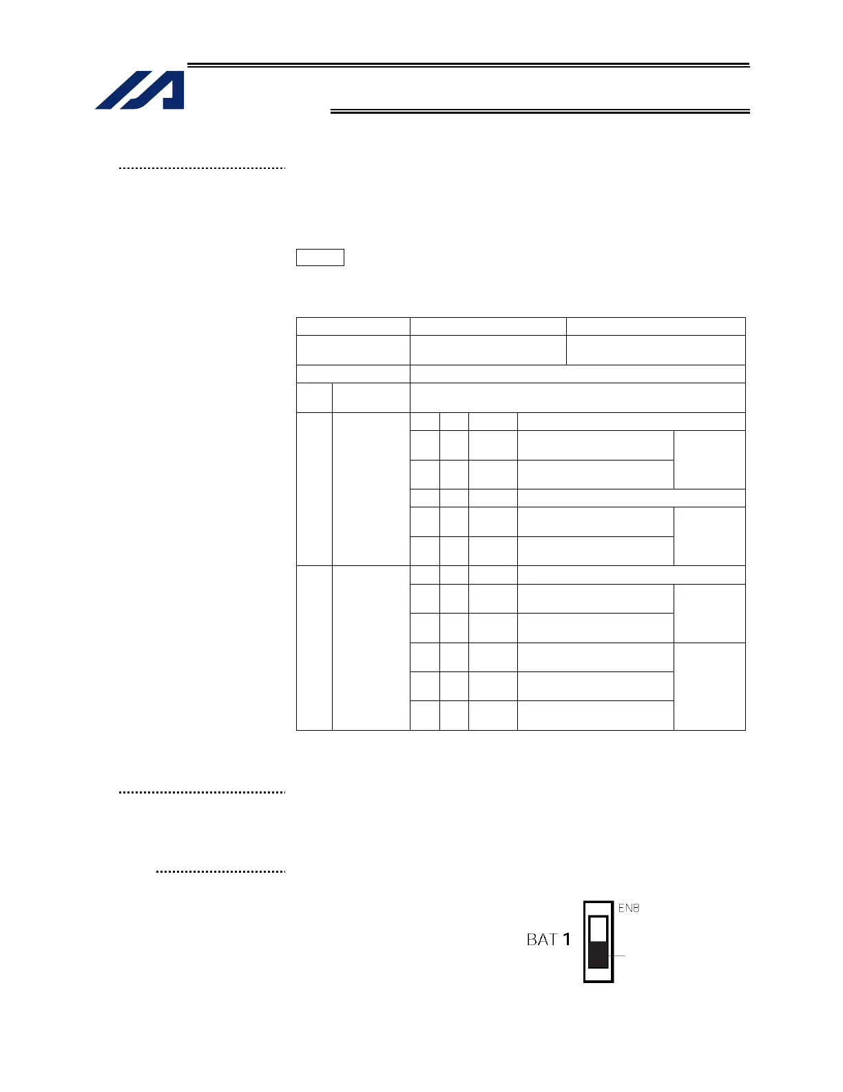
(5) Absolute-data backup
battery enable/disable
switch
This switch is used to enable or disable encoder data backup using the
absolute-data backup battery. The backup is disabled before shipment.
Set the switch to the top position after connecting the encoder/axis-sensor
cables and turning on the power.
Set to the bottom
position to disable.

 Loading...


